We’ve recently started working on a new board–something to monitor and report the current battery level of an automated vehicle. On the previous board (in charge of controlling speed), we had a hand-driven test fixture that we used for system testing. This time around, we would like to make heavy use of support hardware that we can control programmatically. Our goal is to make the system testing for the board just as automated as our unit tests are.
[The speed control board’s test fixture]

Although all of the knobs, switches, and LEDs are fun to play with, the board is still difficult to test. This is, unfortunately, because a large majority of the system testing knowledge for the software running on the board is wrapped up in one or two people’s heads. This makes it difficult for others to be confident their changes didn’t break the system. (Yes, hopefully people don’t commit any code with broken unit tests, but unit tests can’t prove system-level behavior.)
[The battery monitor board]
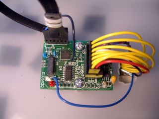
Here is the new board; it’s pretty simple compared to the speed control board. It has three forms of IO: seven digital output bits, two analog inputs, and a CAN bus connection. Our goal is to make automated system tests that send a specific analog signal, give the board some time to process it, and then verify the digital output or CAN bus output matches what we’d expect. The system tests are just like unit tests, except working against the whole board. In order to pull this off, we needed hardware for:
- Programming the board with the newest software
- Generating an analog signal as input for the board
- Reading the digital output from the board
- Sending and receiving CAN bus messages
[Above: USB PIC programmer Below: USB-serial converter]
This picture shows the melabs USB programmer, which we use for programming the board. We chose the melabs device because of its simple command line interface. Also pictured is a USB-serial converter, which we use for manual debugging of the board.
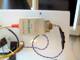
[USB-CAN adapter]
[The minilab 1008]
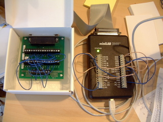
These two pictures show the two devices that control the IO to the board. First is Grid Connect’s pCAN-USB adapter, which allows us to process CAN bus messages to and from the board. Second is the minilab 1008 device from Measurement Computing. The minilab is what delivers analog signals and reads the digital signals to and from the board. Both of these devices were chosen because we were able to easily wrap their C libraries into Ruby extensions.
[The USB hub really ties the room together]
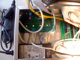
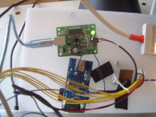
[Battery monitor board mounted to its test fixture]
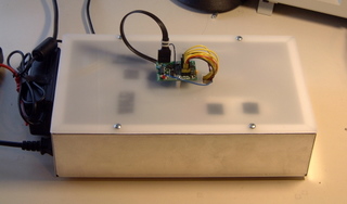
With the help of a USB hub and a little patience, we were able to bundle all of this hardware up into a nice little package. The above picture shows the complete test fixture–two power supplies (USB hub and power for the board), a USB cable running to our continuous integration server, the test hardware box, and the battery monitor board itself. Using Systir, we hope that we can make system testing automated, repeatable, easy, and enjoyable. After we have some more experience actually using this test fixture, we’ll update the Embedded at Atomic Object page with our findings.