
In professional software development, version control systems (VCS) are a critical part of our daily routine, because they allow developers to:
- keep an accurate record of the entire history of a project
- see exactly what changes your team mates are making and how those changes impact the overall project
Hardware designers can benefit by using a VCS for these same reasons.
In this post I’ll describe one setup for using a VCS with your hardware design, using CadSoft EAGLE. EAGLE is a tool for designing circuits and laying out a printed circuit board. It’s very commonly used within the hobbyist community because it’s free for small circuit boards.
This post is not a tutorial on how to use EAGLE or a Version Control System. If you are looking for tutorials on EAGLE, I would highly recommend sparkfun.com. If you’ve never used a VCS before, I would highly recommend Git.
EAGLE Files Overview
In order to structure your hardware repository intelligently, it’s important to understand what files are used by EAGLE and what they are for. EAGLE uses four main file types: Projects, Libraries, Schematics, and Boards.
Libraries
EAGLE uses the concept of Libraries to store components. Each library is stored in a unique file with a .lbr extension. EAGLE libraries store the building blocks used for creating circuits. For each component contained in a given library, the .lbr file includes the definitions of both the symbol and package. These libraries can be shared between users very easily.
Projects
Whenever you create a new project in EAGLE, the software creates a project file called eagle.epf. The project file is really just a container for project settings. It contains references to the libraries that you have used, and some state information about what applications windows were last open. The project file is not a critical design component, and it can be easily recreated by adding existing design files to a new project.
Schematics
The schematic files (.sch) are very important to a project. As you might guess, this is where your all the schematic information is contained. Every component, every net, and every layer that is used in the schematic is contained in the .sch file. Older versions of EAGLE used to store schematic files in binary format, but several years ago they switched to an XML format. This makes it much nicer to use with version control as you can actually see what changes were made, in readable text.
Have you ever wondered what would happen to your schematic if you were to delete one of the library files that contains a component you used in the circuit? The answer is, nothing. That’s because when you add a component to your schematic, EAGLE copies the entire symbol definition into the schematic file. You can come back into your schematic (with the library deleted) and move the component around and wire it up to different nets all you want. The only time EAGLE will try to look at the library file again is if you select Library->Update from the Tool Menu, at which point it will try reload any changes that may have been made.
Boards
Board files are very similar to schematic files, but instead of containing component symbols they contain packages and wires. Just like schematics, all the necessary component information for every component used in the design is contained in the board file. This makes EAGLE designs very portable because you could send someone just a component or board file and they would be able to open it and even make changes without having any of the original libraries.
Backup Files
If you have ever looked at the files contained in your EAGLE project directory, you might have noticed some strange looking filenames that have .b#1, .s#1, or similar extensions. These are actually EAGLE’s built-in attempt at version control. Whenever you make changes to your design, EAGLE saves a backup copy of your board and schematic files. If you don’t delete those files, you can rename them to the appropriate .brd or .sch extension at any time to revert back to an older version of your design. This system is quite limited though, as it can only store 9 past versions. Also, there is no way to easily tell what is different from version to version without using an external diffing tool.
Tools – CAM, DRU, etc.
There are a few other file types that EAGLE uses for miscellaneous purposes. I call these tool files. CAM files (.cam) contain instructions for converting your final board design to a set of Gerber files. The CAM file specifies which layers of the PCB will end up in each Gerber file, and what the output names should be. It also specifies what Gerber output format to use.
DRU files are design rule files. Design rules, as the name indicates, are a set of rules that your design must adhere to. When you run the Design Rule Check, if your design violates a rule EAGLE will inform you with an error.
The information contained in the tool files is also in human-readable text making it a great candidate for version control. Another thing to note is that generally, tool files are not specific to
Version-Control Setup with EAGLE
When using a VCS for software development, you generally create a separate repository for every project. It’s very common for dependencies to be stored in separate repositories and then pulled in to a given project using some sort of dependency management tool like Bundler or NPM. For hardware design, I wouldn’t necessarily recommend the same approach.
One Repo to Rule Them All (Simpler Approach)
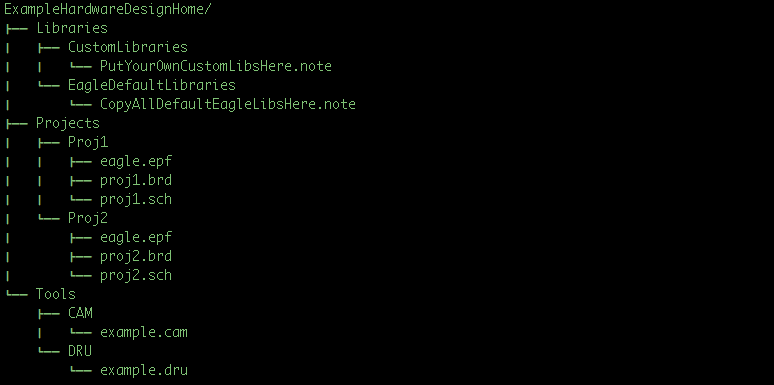
The setup that I use consists of one hardware design repository that contains all my projects, libraries, and tools. I start by installing EAGLE to the default installation location. Then I copy all the bundled libraries into my repo. That way I can add to them or change them over time, and all those changes will be recorded. Don’t put the actual EAGLE application inside your repository. There is no reason to do that. When you open EAGLE modify the Directories for your libraries, projects, and tools, to point to the location inside your repo.
The image below shows an example repository structure. Note that each project is in a subfolder and that the EAGLE application files are not included in the repo.
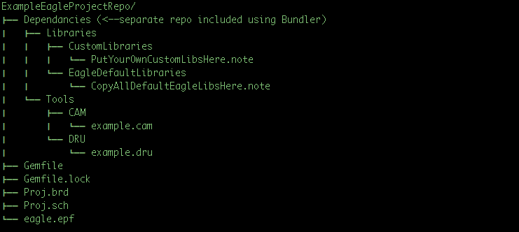
Separated Project Repos (Advanced, Experimental Approach)
If you are more experienced using version control systems or have experience using Bundler, you could use a different approach where you create a new repository for every project—just like we do with software development. In this case you would create separate repository that contains just the bits you want to share between each project. This would include you libraries, CAM files, DRU files, etc. Then you could use Bundler to specify the location and version of the shared library that you want to pull into each project by documenting it in the Gemfile.
Components & Versioning
With using either of these approaches, it’s important to keep in mind how changes to your Libraries might affect older projects. Because all the libraries are in one repository, they are essentially all snap-shot together. That means you can’t use versions of components from two different points in time.
For this reason, I would highly recommend avoiding changes to your components unless you truly want to globally change that component in every design. Because of the way EAGLE stores components in the .brd and .sch files, the change won’t actually bubble into your old designs unless you explicitly run the command to Update Libraries.
I’d love to hear stories or tips from others who are versioning their hardware design files. Please share if you have important lessons learned!