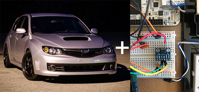
I recently started a fun personal project involving two of my favorite things: cars and software. Modern cars come with plenty of software on board, controlling everything from engine behavior and stability to door locks and entertainment. The software already running on my Subaru does plenty of interesting things, but I’d really like to see more live information from its engine control unit (ECU). So I’ve taken the only logical next step: building a digital gauge.
Of course, I could just buy something and be done with it. I already have good ways to log the data that interests me with off-the-shelf products and a laptop. The truth is, I’m just hopelessly in love with building and playing with things like this, and I tend to learn a lot from these endeavors. So here we go.
I’ve had a lot of fun working through the challenges this little project has offered. Troubleshooting CAN bus communications reminded me of a few good lessons I’ve learned in my software development career.
First, a quick run-down on the components involved:
- BeagleBone – the older white one, almost the same as a BeagleBone Black, running debian Wheezy with 3.13.x kernel for the type of PRU support available
- Adafruit 128×128 1.5” OLED display connected to the Beaglebone via SPI and using fbtft driver
- Adafruit 24 LED Neopixel Ring connected to one of the AM335x’s PRUs (real-time processing units) to drive the timing-sensitive protocol used by the Neopixel LEDs
- MCP2562 CAN bus transceiver connected to one of the AM335x’s CAN controllers
1. Good tools are worth their weight in gold.
Building web and mobile applications for the past 13 years has taught me the value of good tools. Firebug and the Chrome Developer Tools were game changers when it came to easily understanding what is happening under the hood of a web application. So when I ran into a snag communicating over the CAN bus on my Subaru (I could receive but not transmit messages), I went looking for tools that could help me get a clear picture of what was happening.
I started with my trusty voltmeter. It can tell me some very useful things, like the voltage between the Vref (voltage output reference) pin and ground on the first CAN transceiver chip I tried using. But it leaves a lot to be desired reading a 500khz signal. Not the right tool for that job.
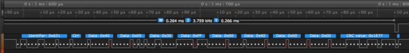
Next up, I borrowed Atomic’s Saleae logic analyzer (which can definitely handle a 500khz signal). I had never used a logic analyzer before. It was like opening up the Networking tab of the Chrome Developer Tools, in terms of both capability and ease of use. Not only can it show high and low bits of a signal, but the Logic application easily decodes valid CAN data.
I could immediately see what was happening on the Tx and Rx lines between the BeagleBone and CAN transceiver chip. It revealed that when my setup tried to transmit a simple CAN frame on the bus, the result was a malformed CAN frame. The data it showed on the Tx and Rx pins also differed in some ways that made me question whether the transceiver was behaving correctly.
(More background: I was using TI’s SN65HVD230 CAN transceiver because it supports the 3.3v logic of the BeagleBone. It also uses a 3.3v supply voltage, leading to questions of whether it can interoperate with CAN devices that use a 5v supply voltage. TI documentation shows that the transceiver has passed various validation tests that prove it interoperates just fine with other 5v transceivers, but at this point, I was starting to develop a degree of skepticism. I’ve used Microchip’s MCP2551, a 5v transceiver, before with no problems.)
2. Blame yourself first; validate assumptions.
My skepticism was growing, but there seem to be plenty of people using the TI CAN transceiver successfully. I still assumed I was doing something wrong and set up a simple CAN bus using an Arduino and CAN bus shield to shorten my test cycle and validate my general setup on the BeagleBone. I wanted to make sure it wasn’t something specific to my Subaru CAN bus or how I had the devices connected for testing in the car that was causing the problem.
With my test setup, I initially had problems receiving messages on the BeagleBone that were sent from the Arduino. Oddly, measuring the voltage between the Vref pin and ground using my multimeter fixed the receiving problem. Time to dig a little deeper…
We hooked up my bench-top test rig to Atomic’s oscilloscope, and with some (ok, a lot) of guidance, took a peek at the rise and fall of the voltage on the CAN bus lines themselves. CAN is a two-wire differential bus: In this case, the two wires normally hover around 2.5 volts (recessive state, a 1 bit) and devices on the bus pull one wire high (5 volts) and the other low (0 volts) to represent a different bit (dominant state, a 0 bit).
The scope let us watch the high and low wires independently, along with the difference between the two. The logic analyzer couldn’t do anything near this sophisticated. With the analyzer attached, receiving messages worked as expected. The voltage ramp up and down seemed ok in this configuration.
This left me with a puzzler. I don’t have much experience troubleshooting apparent electrical problems like this. We just don’t run into that in web development ;) Fortunately, I work with people who do.
3. Get another opinion.
When I told my coworker Job how hooking up measurement devices allowed me to receive CAN messages, he mentioned that it sounded like a capacitance problem. I tried a few approaches to solve the problem:
- 0.1uF decoupling capacitor on the voltage supply – no change
- 0.1uF capacitor between the Vref output pin and ground – able to receive messages but not transmit
- Both capacitors in place – able to receive messages but not transmit
That confirmed Job’s suspicion about a capacitance issue causing my problems with receiving messages. But it still didn’t transmit.
4. Try a different approach.

Using the right tools gave me a lot of insight into the things that were working correctly. Blaming myself first and validating assumptions left me with confidence that I was doing things right (within reason). But none of that pointed immediately at a root cause of my problems. I decided to follow the hunch that a different transceiver might not have the same problems.
The Microchip MCP2562 supports variable input logic levels (1.7v to 5v), uses a 5v supply, and is the successor to the MCP2551 I used successfully in the past. One quick order from Mouser and a little fine-pitch soldering later, and I was ready to give it a try.
Drumroll… SUCCESS! I was able to receive and transmit CAN messages on my Subaru’s bus on the first try with the new transceiver chip in place.
There could be a number of reasons why I was unable to transmit using the TI transceiver chip. It could have been a bad batch, it could have been damaged by static discharge, or the breakout board it came on may have had problems. At the end of the day, I was just happy that I had a working setup for CAN communications.
Where you able to decode the can messages?