Article summary
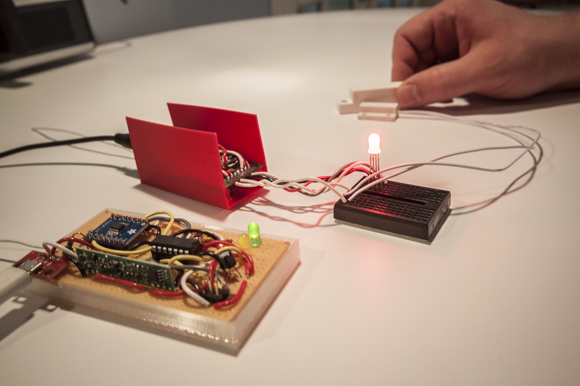
The bathroom on the main floor of our office is down a short hallway, so we can’t see whether the bathroom is available without looking around the corner. To solve this problem, we made an Arduino-based monitor for a reed switch (a magnetic switch) on the door, setting an LED red or green to indicate whether the bathroom is occupied or available.
As Atomic has grown, we’ve gradually had more contention for the upstairs bathroom, and now people are working downstairs as well. Rather than running downstairs to check if the second bathroom was available, I decided to set up a second door switch and build a radio network to broadcast availability.
Deliberate Practice
This was a personal project, so I did things the hard way to learn more about how the fundamental infrastructure worked. For example, I used short-range radio transmitters and receivers that forced me to encode and decode the raw radio signal myself. If this had been client work, I would have used a transceiver that handled signal encoding out of the box, greatly simplifying things. I could have also built it with Arduinos and WiFly shields and just used the local wireless network, but the total BoM cost would have been significantly more (> $200), and I liked the challenge of using ATtiny84s and cheap radio parts. All told, it came to about $30.
Besides, personal projects like this are perfect opportunities for deliberate practice — building functionality like this from scratch inevitably teaches me more about the problem domain than just installing a library. Even though what I build doesn’t always hold up to “real” usage, I’m still more informed about the design trade-offs made by common implementations, and better understand how to use them effectively.
Signal Encoding
Those radio parts use ASK (“Amplitude-Shift Keying”) or OOK (“On-Off Keying”), which means the signal is encoded by changing the amplitude (ASK) or toggling it on and off (OOK). Other carrier styles include FSK (“Frequency-Shift Keying”) or PSK (“Phase-Shift Keying”), which encode information by varying the timing of a carrier wave. If my receiver was a ship lost at sea, trying to find and move towards a lighthouse, OOK would be a light that blinks out a message in Morse code, while FSK would have a light that stays on, but changes color — in the dense fog of radio noise, it’s easier to keep track of the signal if it remains on.
Unfortunately, my ASK/OOK-only parts and the digital logic of my microcontroller restricted me to OOK. I can’t just stream the binary data as-is, either — if there are several 0 or 1 bits in a row, the signal will stay still too long and fade into random turbulence. My transmitter gets around this is by using Manchester Coding: rather than using logic low and high for 0 and 1, it uses falling and rising edges. That way, there is movement during every bit transfer. If several falling edges for ‘0’ bits are sent in a row, it will include rising edges between them to set up for another fall. (It doesn’t matter whether falling edges are 0 and rising edges are 1, or vice versa, so long as the transmitter and receiver agree.)
Using Manchester coding also means that the signal is “self-clocking”: Every bit leads to one or two beats in the rhythm of the signal, and the receiver can analyze the timing to figure out the baud rate (“clock recovery”) as the signal streams in. The consistent timing also makes it easier to distinguish the signal from general radio noise.
How it Works
I made a C library (“spooky“) that ties these together. It automatically handles Manchester encoding and decoding, as well as automatic clock recovery. To encode data, enqueue an outgoing message and call a step function at a regular interval (e.g. from a timer interrupt), which indicates whether the signal line should be set to logic low or high, be left as-is, or that the transfer is complete. To decode, sink the current high/low state of the receiver line at a regular interval, and a callback will be called with any successfully decoded messages. (It handles variable-length transfers and does basic checksumming, so scrambled messages will be filtered out.)
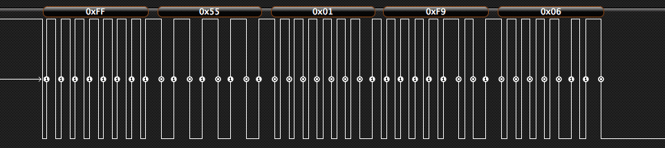
Since the receiver doesn’t know the rate at which the signal is being sent, it needs to log the signal state as often as it can while maintaining consistent timing (oversampling). Having several data points between transitions helps to compensate for small amounts of timing variation. It tracks the signal edge times with a ring buffer, and once it sees the expected header of several approximately evenly-timed transitions (0xFF, or 11111111 in binary) followed by 8 that are twice as long (0x55, or 01010101), it’s probably found a signal. It then watches for length and checksum bytes, and then a payload of the expected length, all transmitted at the same rate. If the checksum matches the data received, the message is passed to the rest of the application.
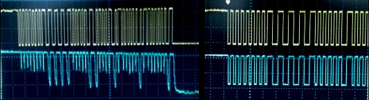
I got stuck on the project for a bit, because the data sheet for the receiver was way off — it claims the receiver could do 4800 bps, but the falling edges for the signal were really sloppy. If I transmit at 667 bps, about 7x slower, the signal is much clearer. (Someone else at Sparkfun ran into the same issue.) At first I didn’t have an oscilloscope at home, just a logic analyzer, so I didn’t see that I had an analog signal problem.
Sharing the Airwaves
Since multiple transmitters will be communicating on the same frequency (in this case, the upstairs and downstairs bathroom doors), it’s also important to handle when the signals aren’t received properly. The devices are on 434 MHz, an amateur-allocated radio frequency also used by things like garage door openers. Sharing the airwaves means I shouldn’t block the frequency for long.
The open/closed state only occasionally changes, so periodically repeating the signal is sufficient – the endpoints normally transmit once every 5 seconds (with some random variation, seeded by the endpoint ID), but transmit more often if the door state has changed recently. Since the actual transmission takes 50-100 msec, it’s pretty unlikely that they’ll collide multiple times in a row. Between the quick bursts, long rests between them, and relatively short range (at most a few hundred feet), they should have little impact on other radio systems in the immediate area.
Now, the system endpoints are able to communicate pretty reliably over a homemade radio link, but, where does the data go? Watch out for part two, in which I make the receiver into a USB device.