
I recently got on the Stranger Things bandwagon, by which I mean that I binge-watched Season 1 in one weekend… and then I recreated the “alphabet wall” that Hawkins-resident-and-eternally-anxious-mother Joyce Byers has in her house (um, spoilers, I guess?).
If you’re a fan of the show, or need a way to receive messages from the Upside Down, this post details how to re-create the wall with an ESP8266, Neopixel LEDs, some craft supplies, Eggos, and a little bit of time.
(This version receives messages over a serial connection with a laptop. Come back tomorrow to learn how to connect the project to the internet and send messages wirelessly!)
The finished product looks like this:
I had a couple of goals for this project: I wanted to keep things relatively simple and take shortcuts where I could, so that I could finish the project in one weekend and avoid it spilling over into Thanksgiving week. Secondly, I have a giant pile of electronics and dev boards at home (I’m not the only one… right?), so all of the electronics that I used were parts that I had on-hand.
Ready to build an alphabet wall of your own? Let’s get started!
What You’ll Need
Electronics
- ESP8266 (I bought the Huzzah breakout board from Adafruit)
- FTDI cable or other way of programming the ESP8266
- Addressable RGB LEDs (I used leftover Neopixels, but you could also use something like these )
- 5V power supply “wall wart”
- 22-24 AWG wire and heatshrink
- Soldering iron and solder
Decorative
- 14” x 17” shadow box
- Floral wallpaper
- “Wood” colored paper
- Black paint
- Paint brush
- Glue stick
- Thin decorative wire (since my LEDs were behind the wallpaper)
- Paper and pencil to trace the picture
- Hole punch
- Scissors, a hot glue gun + glue sticks, an X-Acto knife
Setting Up Your ESP8266 (Huzzah)
The ESP8266 is essentially a wifi-enabled Arduino board. I had previously tried to buy some ESP8266 modules on their own, but I had a lot of issues. The Adafruit Huzzah breakout board is a little more expensive, but I was able to get it up and running quickly instead of spending several hours debugging power supply problems (as I had done before).
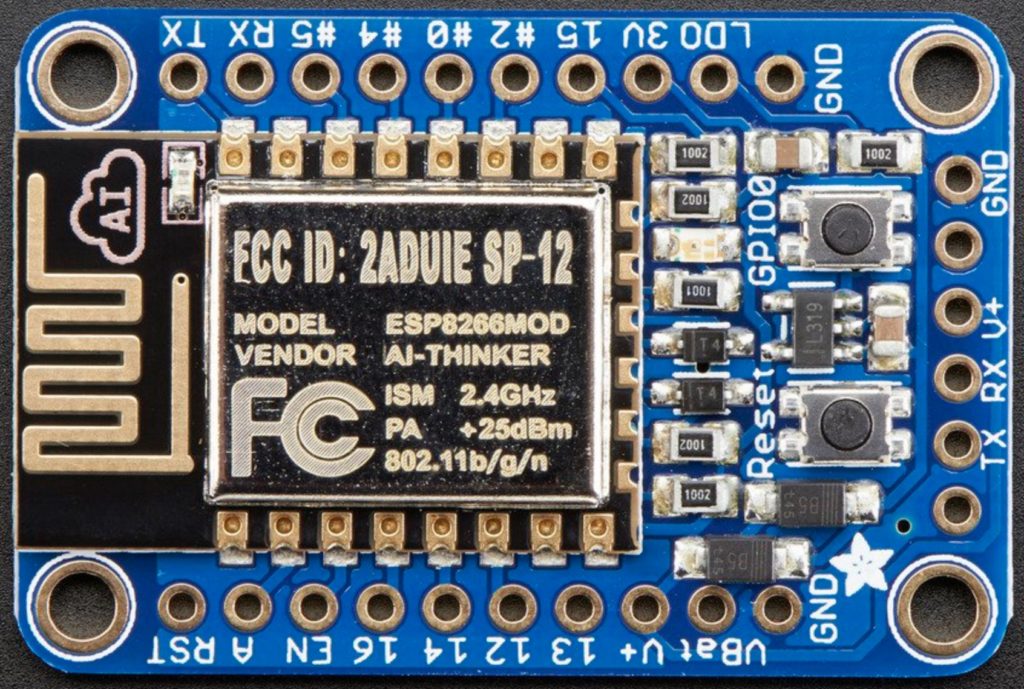
First, you will need to solder the header pins on the breakout board as shown here.
Next, plug in your FTDI cable (as shown here). Make sure that you plug the cable in the right way (so that the black wire is connected to ground, as shown in their instruction photos).
I used Arduino IDE to program the ESP8266. Install Arduino, Version 1.6.4 or greater.
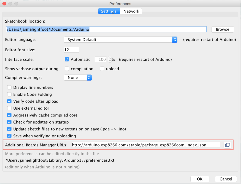
Next, you’ll need to install support for the ESP8266 board. Open Arduino, click the Arduino menu, and select Preferences. In the “additional board URL parameters,” enter in https://arduino.esp8266.com/stable/package_esp8266com_index.json.
Go to Tools > Board > Board Manager, and type in ESP8266 (by esp8266 community). Install the ESP8266 library.
I recommend using one of the example projects to test your board out. Look under File > Examples, and scroll down in the menu. You should see ESP8266 examples. Pick one, like “Blink,” and open it.
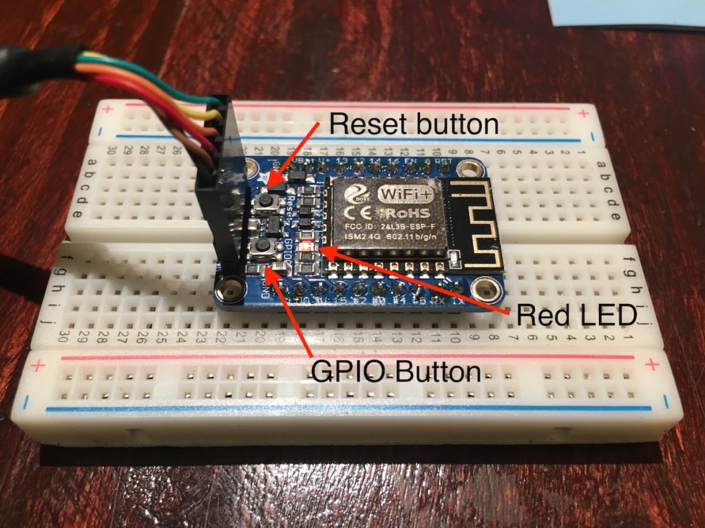
On the ESP8266 Huzzah board, you should see two buttons. One is marked GPIO, and one is marked RESET. Push down the GPIO one, and as you’re holding it down, push the reset button. You should notice the red LED on the board going from full brightness to half brightness. The low-brightness state lets you know that the board is ready to be programmed. In Arduino IDE, click “Upload” (after selecting the correct Port and Board from the Tools menu) and see if it works.
Neopixel LEDs
As mentioned earlier, I used Neopixel RGB LEDs because I had them on hand. Before you put them in the decorative case, it’s a good idea to test them out. Here’s a primer on Neopixels. They’re addressable LEDs, meaning that you only need one IO pin to control them, plus power (3V) and ground. There’s a limit to how many Neopixels you can control at once, but 26 (the number of letters in the alphabet) is way below that limit.
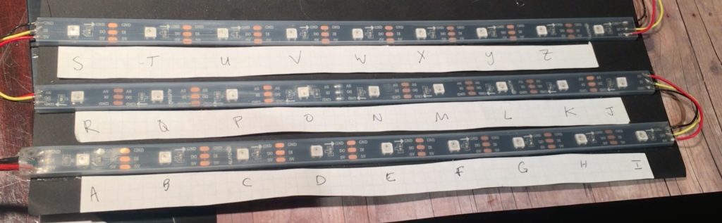
I cut 26 LEDs into three strips for A-H, I-Q, and R-Z and connected them with wire (ground to ground, power to power and DI0 to DI0). I’ve connected the power and ground pins to 3V and GND on the ESP8266 board, and DI0 to Pin 2 on the ESP8266 board.
Sketch > Include Library > Manage Libraries Find the Adafruit Neopixel library and install it.
In your Arduino sketch, include the Neopixel library. You’ll also need to define the pin that will be connected to the DI0 line, and how many LEDs you’re controlling, and then pass these into Adafruit_Neopixel() to define the strand of LEDs to control in later steps.
#include <Adafruit_NeoPixel.h>
#define PIN 2
#define NUMPIXELS 26

Adafruit_NeoPixel pixels = Adafruit_NeoPixel(NUMPIXELS, PIN, NEO_GRB + NEO_KHZ800);
In your setup function, you will want to write pixels.begin() to initialize your strand of LEDs.
void setup() {
    pixels.begin(); // This initializes the NeoPixel library.
}
In the loop function, you can turn LEDs on or off by calling setPixelColor(...) and then pixels.show(). Potential timesaver: If you don’t remember to call the show() function, you won’t see your changes. ;)
void loop() {
  pixels.setPixelColor(PIXEL_NUM, pixels.Color(RED_VALUE, GREEN_VALUE, BLUE_VALUE));
  pixels.show();
}
I wanted to be as close to the show as possible, so I took this picture and color matched the LEDs as best I could. I put the setPixelColor(...) call inside a loop and lit up all 26 LEDs, adjusting the color values with the help of a color hex code finder.
I wrote a struct that contains the letter of the alphabet as a char, plus three int values for red, green and blue (RGB).
struct colorCode {
    char letter;
    unsigned int red;
    unsigned int green;
    unsigned int blue;
};
Here’s the set of color values I came up with, plus the order to account for how I set up my LED strips:
struct colorCode alphabet[26] = {
    {'a', 255, 255, 225}, // A 0 white
    {'b', 0, 0, 225}, // B 1 dark blue
    {'c', 210, 30, 210}, // C 2 magenta
    {'d', 103, 228, 255}, // D 3 light blue
    {'e', 0, 0, 225}, // E 4 dark blue
    {'f', 255, 255, 0}, // F 5 yellow
    {'g', 255, 0, 0}, // G 6 red
    {'h', 0, 255, 100}, // H 7 green

    /* second row, reverse order */
    {'q', 210, 30, 210}, // Q 8 magenta
    {'p', 103, 228, 255}, // P 9 icy blue
    {'o', 210, 30, 210}, // O 10 magenta
    {'n', 255, 0, 0}, // N 11 red
    {'m', 255, 255, 0}, // M 12 yellow
    {'l', 103, 228, 255}, // L 13 light blue
    {'k', 0, 0, 225}, // K 14 dark blue
    {'j', 255, 0, 0}, // J 15 red
    {'i', 0, 255, 100}, // I 16 green

    /* new row, normal order */
    {'r', 103, 228, 255}, // R 17 light blue
    {'s', 255, 255, 225}, // S 18 white
    {'t', 255, 255, 0}, // T 19 yellow
    {'u', 0, 0, 225}, // U 20 dark blue
    {'v', 255, 0, 0}, // V 21 red
    {'w', 0, 255, 100}, // W 22 green
    {'x', 255, 255, 0}, // X 23 yellow
    {'y', 210, 30, 210}, // Y 24 magenta
    {'z', 255, 0, 0}, // Z 25 red
};
The next blog post will show how to connect your alphabet board to the internet with MQTT, but for now, you can test your LEDs and send messages by setting up Serial (no, not the podcast) in your Arduino sketch:
void setup() {
    Serial.begin(9600); // so we can input messages
    delay(10);
    pixels.begin(); // This was already here from the Neopixels step
}
Inside our loop function, read in a letter from the serial buffer, and print it out:
void loop() {
    int i;
    byte Byteread;

    if (Serial.available()) {
        byteRead = Serial.read();

        int j = getIndexOfLetter(byteRead);
        if (0 < j && j < NUMPIXELS) {
            int red = alphabet[j].red;
            int blue = alphabet[j].blue;
            int green = alphabet[j].green;

            // set LED and show it
            pixels.setPixelColor(j, pixels.Color(red, green, blue));
            pixels.show();

            // after 1.5 seconds
            delay(1500);
            // clear pixels,
            clearAllPixels();
            // then wait before moving onto the next character
            delay(250);
        }
    }
}

/* Helper function that gets the index of a given letter
from the alphabet RGB data structure */
int getIndexOfLetter(char letter) {
    for (int i=0; i<NUMPIXELS; i++) {
        if(alphabet[i].letter == letter) {
            return i;
        }
    }
    return -1;
}

/* Helper function that clears all the pixels */
void clearAllPixels() {
    for(int i=0;i<NUMPIXELS;i++)
    {
        pixels.setPixelColor(i, pixels.Color(0, 0, 0));
    }
    pixels.show();
}
Note: similar to the ESP8266 example, you can look for Neopixel example projects to get started under File > Examples.
Once you’ve got the serial example working, and you can type in A-Z and see the correct LEDs light up in the correct colors, let’s add some style!
Craft Part
You can make this any size you want. I chose a 14″x 17″ shadow box.
First, I took the photo from the show and blew it up 400% and traced the LED locations and letters onto some big sheets of paper. The spacing of the LEDs–particularly the “Q” that is way out on the side–meant that I had to cut up the LED strips.
Next, using the paper, I cut into the foam backing that was in the shadow box so that there were spaces for the LED strip portions. I didn’t realize that it had foam when I bought it, but it worked out well since I didn’t have “string” LEDs and had decided to hide the LED strips behind the wallpaper.
I glued the LED strips into place with a hot glue gun. Next, I soldered the cut pieces together using small pieces of wire, connecting ground, DI0, and power (3V), respectively.
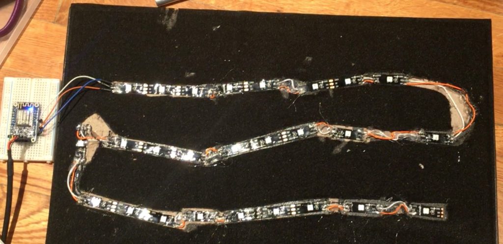
This is a good time to plug in your ESP8266 and make sure that your LEDs still work as expected (hint: if your LEDs are all red instead of the expected colors, this means there’s likely a faulty ground connection somewhere). Consider using something (I used hot glue) to insulate your soldered connections and hold the wires in place.
I took the 5V power supply, cut off the barrel connector, and stripped the wires. I soldered power (5V) to VBAT on the ESP8266, and ground to ground. Eventually, I secured the ESP8266 to the back of the shadowbox, meaning that I ran ground, power and signal wires inside the shadow box, to my LEDs. Alternatively, you could store the ESP8266 inside the shadow box. Whatever you decide, cut wire lengths accordingly, connect your ESP8266 to the power supply and LED strip, and secure in place.
Next, I cut a piece of the floral wallpaper to size. I bought a roll of floral wallpaper, but you could do this with scrapbooking paper instead. I tried to match the floral pattern on Joyce Byers’ walls, but mine is much cheerier than hers. The wallpaper I used was very thin, and a lot of LED light bled through. I turned all the LEDs on, and traced the LED locations onto the wallpaper. I cut a piece of black paper that was the same size as the wallpaper, and glued the two together with a glue stick. The extra layer of paper prevents the LED light bleed-through.
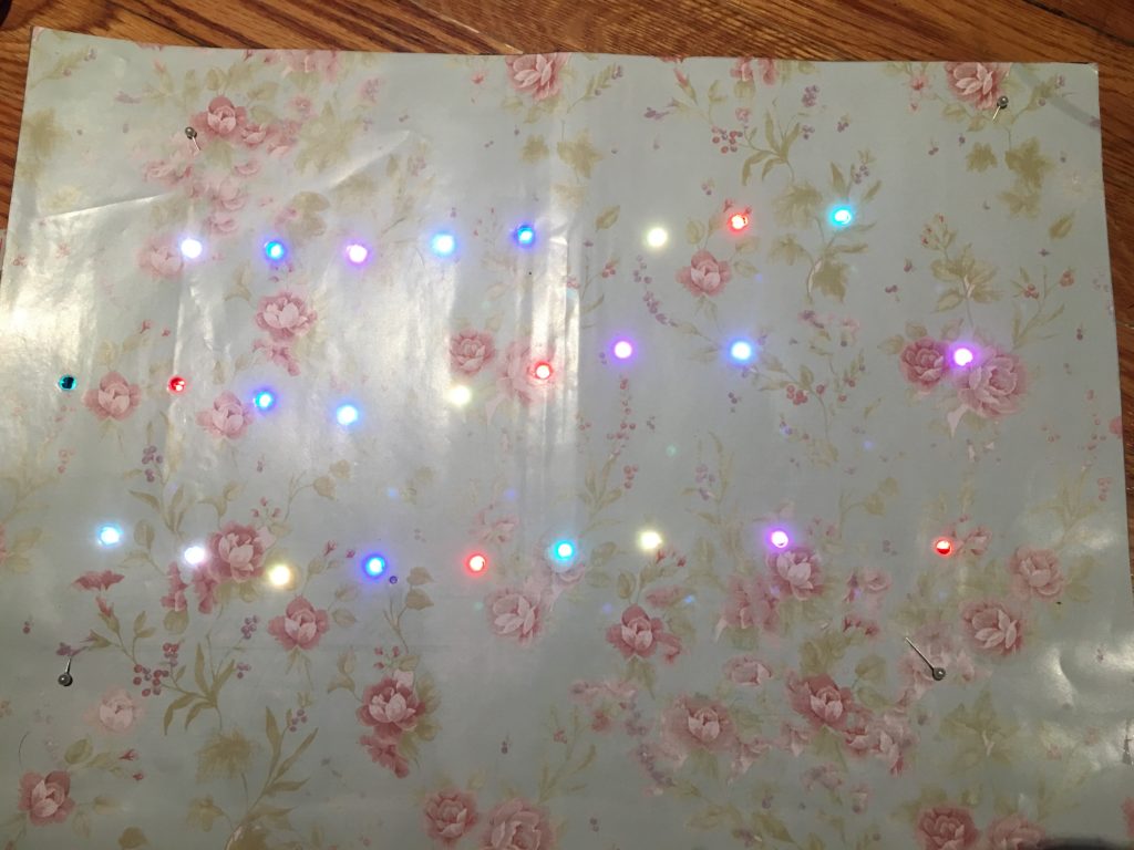
Then, I used a punch to create holes where I had traced. The result is a double-thick piece of 14″ x 17″ paper with holes cut where the LEDs will be. Measure twice, punch once (well, 26 times) so that you get the alignment right. Once you’ve got it right, glue that on top of the LEDs.
Note that a lot of this craft portion would be easier with string style lights! :)
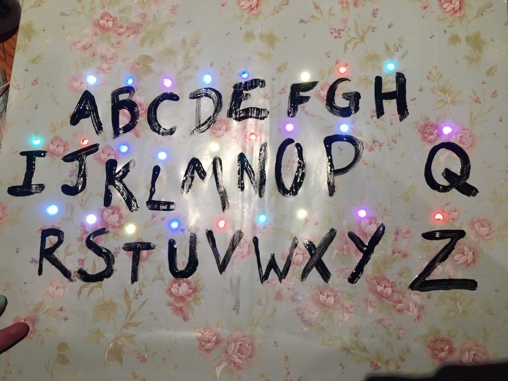
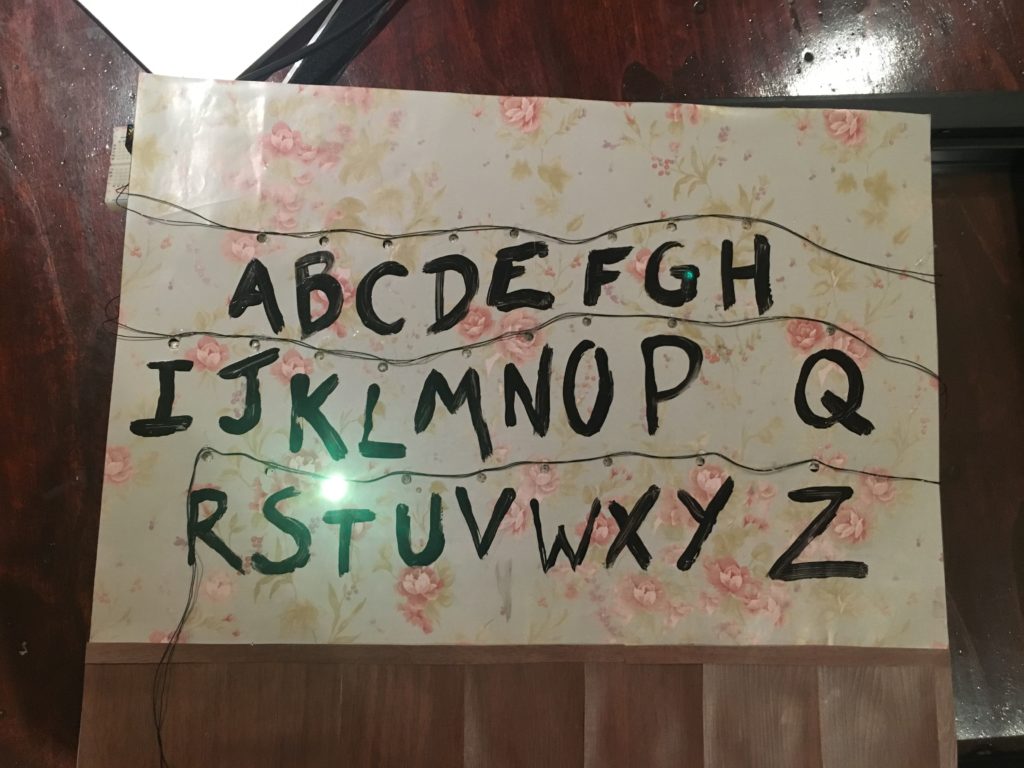
Next, pour out some black paint and paint the letters of the alphabet, Joyce-style. I practiced this a few times on scratch paper so that I got the paint thickness and style right.
After that dried, I added 26 gauge black wire to mimic the string lights style in the show. I used a hot glue gun for this part.
Lastly, I added fake wood paneling at the bottom using scrapbook paper. The end result looks like this:
Altogether
#include

#define PIN            2
#define NUMPIXELS      26

Adafruit_NeoPixel pixels = Adafruit_NeoPixel(NUMPIXELS, PIN, NEO_GRB + NEO_KHZ800);

struct colorCode {
  char letter;
  unsigned int red;
  unsigned int green;
  unsigned int blue;
};

struct colorCode alphabet[26] = {
    {'a', 255, 255, 225},   // A 0 white
    {'b', 0, 0, 225},       // B 1 dark blue
    {'c', 210, 30, 210},    // C 2 magenta
    {'d', 103, 228, 255},   // D 3 light blue
    {'e', 0, 0, 225},       // E 4 dark blue
    {'f', 255, 255, 0},     // F 5 yellow
    {'g', 255, 0, 0},       // G 6 red
    {'h', 0, 255, 100},     // H 7 green

    /* second row, reverse order */
    {'q', 210, 30, 210},    // Q 8 magenta
    {'p', 103, 228, 255},   // P 9 icy blue
    {'o', 210, 30, 210},    // O 10 magenta
    {'n', 255, 0, 0},       // N 11 red
    {'m', 255, 255, 0},     // M 12 yellow
    {'l', 103, 228, 255},   // L 13 light blue
    {'k', 0, 0, 225},       // K 14 dark blue
    {'j', 255, 0, 0},       // J 15 red
    {'i', 0, 255, 100},     // I 16 green

    /* new row, normal order */
    {'r', 103, 228, 255},   // R 17 light blue
    {'s', 255, 255, 225},   // S 18 white
    {'t', 255, 255, 0},     // T 19 yellow
    {'u', 0, 0, 225},       // U 20 dark blue
    {'v', 255, 0, 0},       // V 21 red
    {'w', 0, 255, 100},     // W 22 green
    {'x', 255, 255, 0},     // X 23 yellow
    {'y', 210, 30, 210},    // Y 24 magenta
    {'z', 255, 0, 0},        // Z 25 red
  };

byte byteRead;

void setup() {
  Serial.begin(9600); // So we can input messages
  delay(10);
  pixels.begin(); // Initialize strand of LEDs
}

void loop() {
    int i;
    byte Byteread;

    if (Serial.available()) {
        byteRead = Serial.read();

        int j = getIndexOfLetter(byteRead);

        if (0 < j && < < NUMPIXELS) {
          int red = alphabet[j].red;
          int blue = alphabet[j].blue;
          int green = alphabet[j].green;

          // set LED and show it
          pixels.setPixelColor(j, pixels.Color(red, green, blue));
          pixels.show();

          // after 1.5 seconds
          delay(1500);
          // clear pixels,
          clearAllPixels();
          // then wait before moving onto the next character
          delay(250);
        }
    }
}

/* Helper function that gets the index of a given letter
from the alphabet RGB data structure */
int getIndexOfLetter(char letter) {
    for (int i=0; i < NUMPIXELS; i++) {
        if(alphabet[i].letter == letter) {
            return i;
        }
    }
    return -1;
}

/* Helper function that clears all the pixels */
void clearAllPixels() {
    for(int i=0;i < NUMPIXELS;i++)
    {
        pixels.setPixelColor(i, pixels.Color(0, 0, 0));
    }
    pixels.show();
}
End Result
See the project on GitHub here.
Part 2 (coming tomorrow!) builds on this post, allowing you to take advantage of the ESP8266's wifi capabilities and send messages wirelessly.