My brain thinks about software systems in terms of boxes and arrows. It’s a clear enough representation of most dataflow paradigms and easy to draw on a whiteboard. One problem with boxes and arrows is that not everybody maps the same concepts to the same shapes. Should a database be a cylinder shape? Do circles represent something different than squares? What do dashed lines mean? In a recent project, we used C4 diagrams to represent software systems. Admittedly these are still just boxes and arrows. But, the standardized diagramming language creates a level playing field for all audiences. I’ve also found that the distinct levels help me to focus my diagrams on the appropriate scope.
Understanding the C4 Model
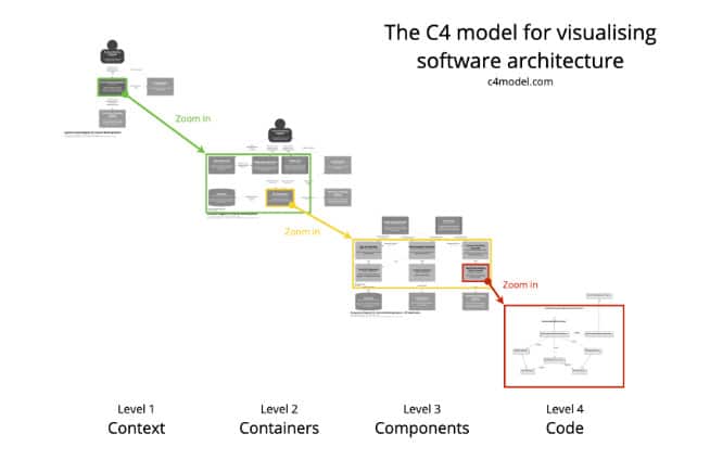
C4 diagrams, created by Simon Brown, represent a hierarchical approach to software architecture diagramming. The C4 model stands for Context, Containers, Components, and Code, allowing for visualization at different levels of detail:
- System Context diagram: Provides an overview of the core systems’ roles in interacting with users and other external systems. (Solutions at the level of a non-technical stakeholder)
- Container diagram: Zooms in on an individual system to understand what independently deployable containers comprise that system. (Databases, web apps, mobile apps, backend servers, etc.)
- Component diagram: Presents a more detailed look at the individual components within a container representing the abstractions a developer might consider. (Controllers, repositories, services, data access layers, etc.)
- Code diagram: Represents of a component by showing individual code elements. (Requests, database connections, dependencies, etc.)
One of the key strengths of C4 diagrams is the consistent conventions. This standardization means that, once you’re familiar with the C4 model, you can easily read and understand C4 diagrams created by others, regardless of the specific project or domain. This consistency eliminates the learning curve typically associated with interpreting new architectural diagrams, making C4 an efficient communication tool across different teams and projects.
It’s worth noting that the popularity of C4 diagrams has led to their experimental integration into widely-used diagramming tools. Both Mermaid and PlantUML are currently adding C4 diagram support, which will further increase their accessibility and ease of use for many developers.
Strengths of C4 Diagrams
C4 diagrams excel in bridging gaps across developers and stakeholders. They provide a consistent diagramming language accessible to both technical and non-technical audiences by enforcing clear abstraction levels.
Consistency in diagramming is crucial. When different team members use different diagramming languages, there’s always a brief learning curve to understanding the diagram before you can even consider the content. Additionally, if a strong foundation of system-level diagrams is established, then it becomes easy to demonstrate proposed changes to the system because deltas are clearly identifiable.
In practice, the System Context and Container diagrams often prove most effective for improving team communication and alignment by clearly documenting a ubiquitous language that can be used to discuss the systems at hand.
Limitations and Pitfalls
Despite the strengths of this type of diagram, there are drawbacks.
Complexity in Large Systems
For large, complex systems, Container and Component diagrams can become overly complicated, resembling a “spaghetti mess” of boxes and arrows. This can lead to significant time spent on diagram arrangement rather than productive work.
Despite this challenge, these large systems are the ones that most benefit from consistent documentation. In these cases, I’ve found myself segmenting the system context into multiple regions.
Diminishing Returns at Lower Levels
While higher-level diagrams (System Context and Container) consistently provide value, the usefulness of Component and Code diagrams can vary.
Component diagrams may be helpful in some cases but are not always necessary. I find them useful when discussing data flow through a system with less experienced developers. But, I tend to think that maintaining comprehensive, long-lasting component-level diagrams is a burden without enough benefit. Rather than documenting each container’s components, I prefer consistent patterns and abstractions throughout the system so that all containers have roughly the same components and don’t require documenting.
I find that Code diagrams lead to micromanagement and reduced developer autonomy. In many cases, well-written code and effective documentation prove more valuable than Code-level C4 diagrams. Anybody that would care about the level of detail presented in a Code diagram should just be reading and reviewing the source code. In some cases, IDEs or other tools might be able to generate Code diagrams for you.
Best Practices for C4 Diagrams
In summary, these points will help to maximize the benefits while avoiding pitfalls:
- Focus on high-level diagrams (System Context and Container) for maximum impact.
- Use Component diagrams carefully, only when they add clear value.
- Avoid Code-level diagrams in most cases to prevent micromanagement.
- For large systems, consider breaking diagrams into smaller, more manageable sections.
I have found C4 diagrams to be a valuable tool for visualizing and communicating software architecture at various levels of abstraction. They excel at bridging communication gaps and aligning teams.
However, their effective use requires careful consideration. Focusing on higher-level diagrams and using more detailed levels carefully will help ensure that C4 diagrams serve as an asset rather than a burden in your system documentation.