Article summary
Everything is better with LEDs, including shoes! When my friend and co-worker Rachael got married, I wanted to give her something really special as a wedding gift. After seeing some DIY LED shoes online, I decided to create my own.
Let’s make some shoes! 🎶
The Inspiration
My last name was not the inspiration for the shoe, but realizing the connection later made for a good pun (other good puns might include “LEDfoot”).
The actual inspiration for my project was this pair of LED shoes, shared by @chthono and shown at Maker Faire Tokyo:
今朝できたばかりのLEDハイヒール汎用版。#MakerFaireToky2017 のD-01-10、SRSIVブースにて明日も展示しています。中身はただのArduino Leonardo互換ボード&HT16K33ですから、その場でこれのプログラムを組んでみたい方もどうぞ。 pic.twitter.com/3jqNVafNHj
— くとの (@chthono) August 5, 2017
I liked the effect that the groups of LEDs had, and the style of the shoe. I prototyped a few different designs and settled on the one I liked the best, using LED strips instead of individual LEDs, which greatly simplified the wiring.
The Hardware
My shopping list:
- Shoes (of course!)
- “Skinny” RGB LEDs strips
- 2 LiPo batteries – 3.7v 2000mAh
- 2 “Trinket” boards
- 2 “PowerBoost” regulator boards
- 2 USB micro breakout boards
- Something to hold the electronics under the shoe
- Two switches
- Resistors (300 ohms x 2, 1Mohm x 1)
- 2 capacitors (recommended 1000 uF)
- Piezo sensor
- Wires
- Flexible black “epoxy” (I originally used hard epoxy, and then switched to ultra-black silicone sealant)
- Electrical tape
- Hot glue gun
- Superglue
I already had some LED strips (from my Stranger Things project), but these were too thick for the base of the shoe. Instead, I used “skinny” strips. I bought some Trinket boards, which are Adafruit’s dev boards meant for wearable electronics (shoes are wearable, right?).
I wasn’t sure where to put the batteries, but once I’d developed my design, I filtered my choices based on what would fit under the shoe. LiPo batteries are flat and rechargeable, so I went with that. I bought Adafruit’s regulator board, which takes a micro USB input and charges the battery.
As with most of my hobby projects, I chose convenience over reinventing the wheel, and this was helpful for the shoes, making them very easy to recharge.
The piezo component detects vibration–in this case, every step of the shoe. As briefly described in this post about timekeeping, piezos vibrate when an electric charge is applied to them, allowing them to function as clocks or speakers. Conversely, piezos can generate voltage when they vibrate or bend. In my design, the piezo sensors are placed under the arch of the shoe in a way that allows them to bend when a step occurs.
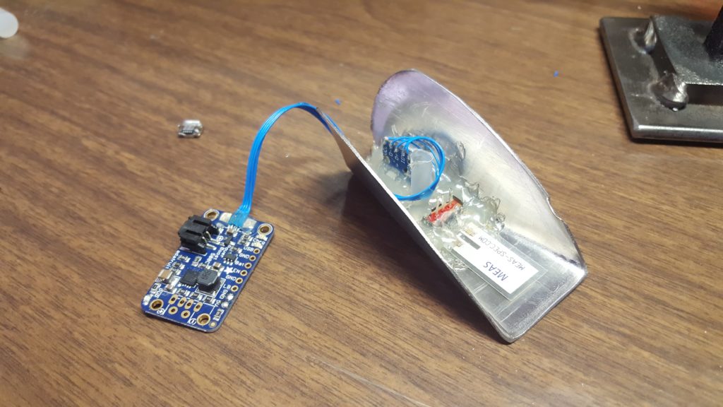
My boyfriend designed and machined two “metal tacos” (shown later) to hold the electronics under the shoe. These are held in place by a screw that connects to a nut welded to the shank of the shoe.
The bottom of each shoe exposes a switch and a micro USB charging port (I gave my friend a 5V, 2.5A phone charger and a Y-cable along with the shoes). We had considered painting the metal part to blend in but decided that we liked the contrast against the black shoe.
If I did this project again, I might try to find shoes that had a platform style so that I could hide the electronics in there, which would simplify the machining and welding aspect of the shoe. Still, I’m happy with the design of the shoe and the metal component.
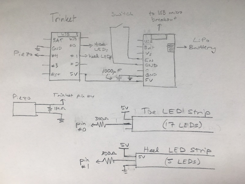
Circuit drawing
Construction
After machining the metal piece and fitting it to the shoe, we cut holes for the switch and the USB port, then covered it in hot glue.
Next, we used thin wire to connect the other components according to the schematic above.
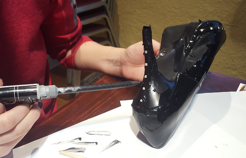
Next, we cut the LED strips and superglued them onto the shoes. Then, we added silicone sealant (originally epoxy) to cover up everything except the LEDs. This helped hide the edges of the LED strips and provided a continuous finish between the vinyl shoes and the black sealant. I taped off the shoes with electrical tape before adding the sealant.
After everything was dry, the shoes looked like this. You can see the nut that is welded onto the shoe shank–this is where the screw connects to hold the electronics in place.
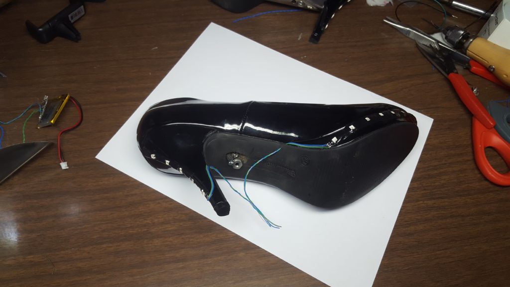
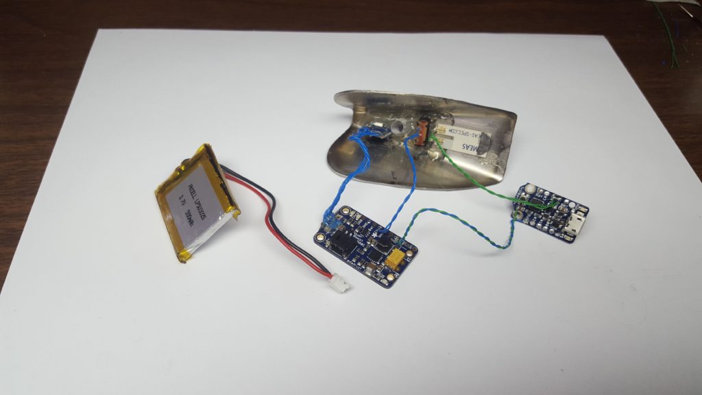
At this point, we connected the loose wires to the circuit boards shown earlier. Here, you can see the charging port (left of the screw) and the switch (to the right).
Finally, we used more sealant to cover the exposed wires and repeated for the other shoe.

Shoe Software
The full Arduino project for this project can be found on GitHub. All of the code is running on the Adafruit Trinket listed in the hardware section above.
Setup
First, we needed to set up the LED constants and variables to use for the LED effects.
/*********** LED-related constants ***********/
#define HEEL_LED_PIN 0
#define HEEL_LED_NUM 17

#define TOE_LED_PIN 1
#define TOE_LED_NUM 5

Adafruit_NeoPixel toeLEDStrip = Adafruit_NeoPixel(HEEL_LED_NUM, HEEL_LED_PIN, NEO_GRB + NEO_KHZ800);
Adafruit_NeoPixel heelLEDStrip = Adafruit_NeoPixel(TOE_LED_NUM, TOE_LED_PIN, NEO_GRB + NEO_KHZ800);
/*********************************************/

/********** Piezo-related constants **********/
#define PIEZO_PIN 2 // analog pins are numbered differently than the digital pins!
/*********************************************/
uint8_t glimmer_upper_limit = 100;
uint8_t glimmer_lower_limit = 50;
uint8_t middle_bright = 75;

#define GROUP_LOW 3
#define GROUP_HIGH 10

uint16_t brightness = 15;
/*************************/
In setup, we initialized the LED strips we created earlier and set all LEDs to OFF. Then, we used the analog pin (measuring the piezo voltage) to generate a random seed for the glimmer effect discussed later (when we call random()).
The interrupt setup and full code can be found here.
void setup() {
    toeLEDStrip.begin();
    heelLEDStrip.begin();

    // Initialize pixels to off
    toeLEDStrip.show();
    heelLEDStrip.show();

    randomSeed(analogRead(PIEZO_PIN));

    interruptSetup();
}
Color cycling
The LEDs cycle through three colors: pink, blue and purple. The main program, or ‘loop()’ in Arduino terms, looks like:
void loop() {
    pinkToPurple();
    purpleToBlue();
    blueToPink();
}
The colors’ RBG values are:
Each of the color transitions (pink -> purple, purple -> blue, blue -> pink) has a different amount of color correction to make in terms of R, G, and B values.
Let me add a disclaimer here that this isn’t the most sophisticated way of cycling through colors. The NeoPixel library offers some examples to neatly cycle through all the colors of the rainbow…my home-brew pink/purple/blue implementation isn’t as neat. Additionally, each of the three transitions do not take the exact same amount of time. That was fine for me–I’m happy with the color cycling as-is.
First, I set the R, G, and B values to the starting color values, and then I decreased R and increased G and B at different rates using some back-of-the-napkin math.
Next, I picked a random number called “group.” This was passed into the functions that set color and brightness. The group is used to randomly choose LEDs to be slightly brighter or dimmer than the “middle brightness” level. The random choice of group means that the same LEDs won’t repeatedly have this effect, but instead, the LED strip will have kind of a “glimmering” effect. Unfortunately, this is hard to capture with my phone camera, so you’ll have to take my word for it. : )
The functions for changing purple to blue and blue to pink are similar.
void pinkToPurple()
{
    // pink (255, 0, 128) to purple (163, 73, 164)

    int i;
    int diff = 512;
    uint8_t r = 255;
    uint8_t g = 0;
    uint8_t b = 128;

    for (i = 0; i < diff; i++)
    {
        if (i % 5 == 0) {
            // time to adjust R
            r--;
        }
        if (i % 7 == 0) {
            // time to adjust G
            g++;
        }
        if (i % 14 == 0) {
            // time to adjust B
            b++;
        }

        uint8_t group = random(GROUP_LOW, GROUP_HIGH); // between 3 and 10
        for (uint16_t j = 0; j < toeLEDStrip.numPixels(); j++) {
            setToeLEDColorWithBrightness(j, r, g, b, group);
            if (j < heelLEDStrip.numPixels()) {
                setHeelLEDColorWithBrightness(j, r, g, b, group);
            }
        }
    }
}

void setToeLEDColorWithBrightness(int j, uint8_t r, uint8_t g, uint8_t b, uint8_t group) {
    if (brightness < middle_bright) {
        decrease_flag = false;
        if (j % group == 0) {
            brightness = random(random_low, random_high);
        } else {
            brightness = middle_bright;
        }
    }

    toeLEDStrip.setPixelColor(j, (brightness * r / 255) , (brightness * g / 255), (brightness * b / 255));
    toeLEDStrip.show();
}
The setHeelLEDColorWithBrightness() function is similar, but it calls the setPixelColor() and show() methods on the heel LED strip.
Piezo to trigger brightness
In the interrupt service routine, we read in the piezo pin and use it to determine if a step has happened. If so, we turn the LEDs up to maximum brightness.
bool decrease_flag = false;

ISR(TIMER1_COMPA_vect) // timer compare interrupt service routine
{
    uint8_t piezoADC = analogRead(PIEZO_PIN);

    if (THRESHOLD < piezoADC) { // if above threshold
        // if first time, jump up to 255
        if (!decrease_flag) {
            brightness = 255;
            decrease_flag = true;
        }
    }

    if (decrease_flag) {
        brightness -= 2;
    }
}
End Result
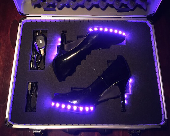
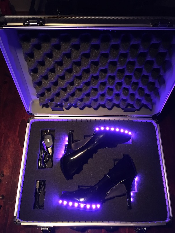
Since fancy LED shoes deserve an equally fancy case, I bought this aluminum box from a hardware store and cut out the foam blocks to hold the shoes and wires.
The shoes take about a minute to fully cycle through the three colors, but here’s a quick (and shaky) time-lapse of it:

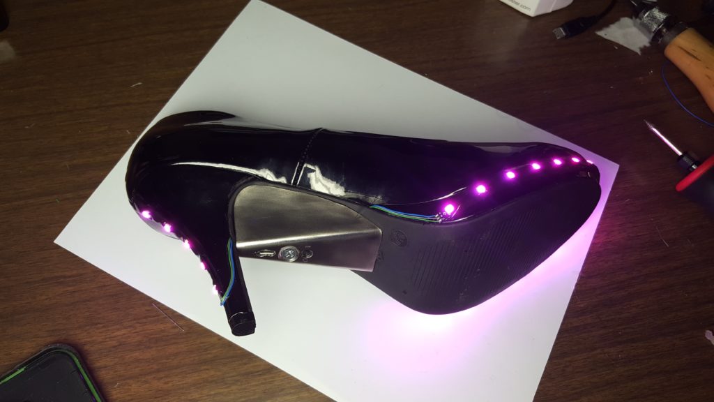
Here’s the “stepping” effect up close:

One last video!
