During a recent augmented reality (AR) mobile app project, my team solved weighty problems with Blender, a 3D creation suite. This piece of software badassery proved a powerful tool and became my latest and greatest obsession. One of my favorite Blender features is the node-based workflow.
Node-Based Workflow
A node-based workflow refers to organizing and linking elements to make up an object or a material. Each element, called a node, symbolizes a certain function on the geometry or the shaders of an object. Once connected, nodes represent the flow of data into an object’s material or geometry.
Glossary
Before we dive any further into nodes, it’s worthwhile to define some common terms I’ll be using. Here’s the vocabulary that helped me Blender better:
scene – space where objects, lights, cameras, and other elements are staged. Each component has its own properties like texture, material, rotation, transformation, and scale.
object – 3D representation made up of many attributes including meshes, and properties including rotation and scale.
mesh – geometric representation that describes an object’s shape, which consists of vertices, edges, and faces.
node – an individual element that signifies graphical operations and, together with other nodes, defines the geometry or material of an object.
world space – coordinate system for an entire scene that constitutes orientations and positions of objects and other components within a 3D environment. As opposed to local space , which refers to the coordinate system of an individual object, light, etc.
geometry – the shape and structure of objects within a 3D scene, which includes the vertices, edges, and faces that make up a 3D model. It also describes the physical characteristics of objects, such as size, position, orientation, and general form.
shader – a computer program that determines how the surface of an object is rendered in computer graphics. Shaders also characterize light-surface interaction, color, texture, transparency, reflectivity, etc.
Blender Node-Based Workflows
Blender features two node-based workflows: geometry nodes and shader nodes.
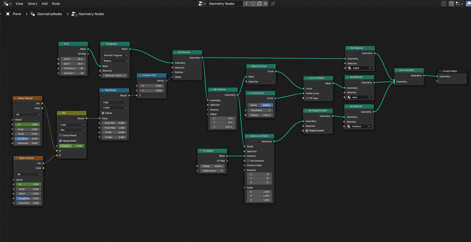
Geometry nodes are networks of interconnected nodes that allow users to procedurally generate, manipulate, and transform a 3D scene.
Shader nodes in Blender act as building blocks for materials. These connected blocks control color, shine, transparency, roughness, etc. for the material of an object.
Where are they?
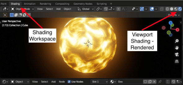
Where to find nodes in Blender’s UI? Let’s take a look at Shader Nodes since finding them has a similar path as Geometry Nodes. Take a look at the Blender UI below:
Above is the 3D viewport (glowing orb), and the Shader Editor (squares and rectangles, aka nodes). The 3D viewport is the place for the user to look at their creation. Note that I have the viewport shading set to rendered , so I can see the colorful emission of the orb object. To do so, make sure you have the shading workspace selected and the viewport shading display button is set to rendered.
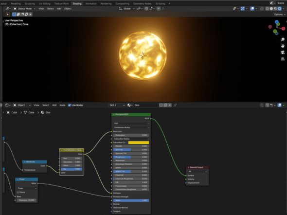
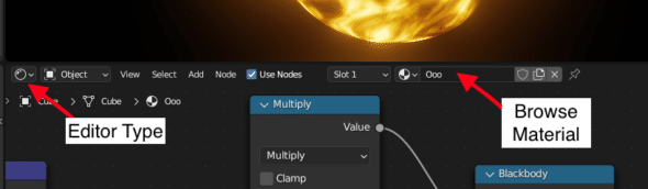
The Shader Editor, like with the Geometry Node Editor, is where the node-based workflow happens. To open, make sure the Editor Type Menu selected is the Shader Editor and set a name for your new material in the Browse Material Menu pictured below (I named the orb Ooo ):
Now that we can see the material and object we are generating, let’s dive into the Shader Editor. This is the place to start adding and connecting nodes to produce a final material output for our object. Here’s what Ooo ’s shader node network (or node graph) looks like:
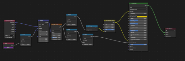
The above image showcases the general structure of a node network or graph. Data flows from left to right in this diagram, starting with input nodes and ending with the final node labeled “output.”
So, how does one use a node workflow? To answer that, let’s zoom in on a node and its components.
Anatomy of a Node
If we inspect a single node, we can start to distinguish it by its different parts: title, properties, and sockets.
Title
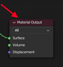
A node’s title or name is located at the top of each node and signifies its usage. In this case, the node Material Output acts as the output for an object’s surface material information.
Properties
Nodes sometimes have specialized properties. For example, Material Output has a target drop-down menu, which currently has All selected. This property lets you specify which rendering engine (Cycles or Eevee) you prefer. Here, All means the render engines share shaders.
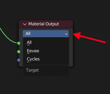
Each node may or may not have specialized properties like this—their components depend on their function.
Sockets
Sockets, the circles on the border of each node, are the main ways of connecting a node to a node network. Each socket represents either an input or an output value, and its color describes the data it handles.
For the example below, the surface socket represents shading for the surface of the object, and volume describes shading for the object’s volume. Notice how they are both bright green—that’s because they deal in shader data. Displacement is purple (or dark blue if you are a Blender doc writer) because it deals in coordinate, normal, and vector data.
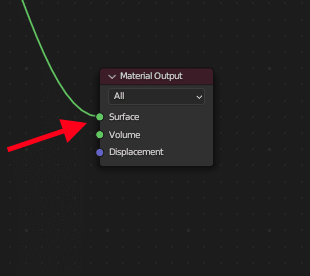
In the context of this node, all of these sockets are inputs , meaning they are located at the left side of the node and feed data into the node for it to perform whatever operation is its specialty.
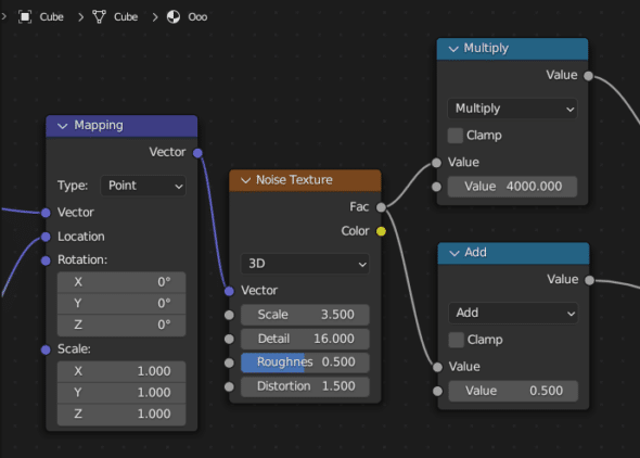
Outputs represent the processed data of a particular node, which is fed into another node. The example below starts with a Blackbody node with an output of color, which represents the RGB color output. Blackbody specializes in transforming black body temperature to color. This has been connected to the Hue Saturation Value node.
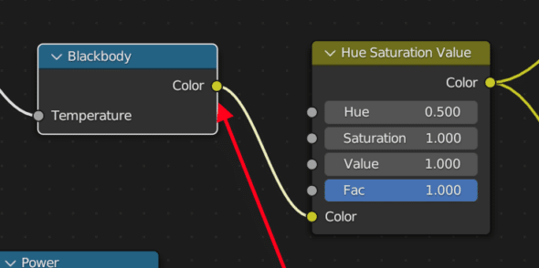
Here the node is taking in a temperature input, performing operations on that data, and producing a color output, which is then fed into the color input of Hue Saturation Value . The Hue Saturation Value node then transforms the properties of hue (hue rotation), saturation (increase or decrease in hue), or value (brightness) on a shader or a texture, and outputs a color.
This workflow represents the flow of data that determines a material’s properties. Sockets act as the ports and connectors to transform that data.
Basic Connections
Beyond a node’s anatomy, I had many basic questions when I started learning Blender. Some of those questions were where do I find them? How do I connect them? How do I disconnect them or delete them? Here are some answers:
Shift + Ain the node editor brings up a menu to choose what node you’d like to use. I consistently hitShift + A + Sto search for a specific node immediately.- Clicking on a node and hitting
Xdeletes a node whileCMD + Ccopies a node. - Connecting a node to another involves clicking on a particular socket and dragging the output to an input. Disconnecting two nodes means clicking on the socket, and then dragging and releasing the connection from the connected node’s input. Alternatively, you can right-click on the connection to initiate the 🔪 and dramatically sever the connection.
Last Thoughts on Node-Based Workflows
Understanding how nodes represent functions performed on data can help you create your desired material, object, and scenes. Both node-based workflows harness Blender’s powerful features and give any maker a huge advantage while creating.
Links to Resources and Faves
Default Cube aka CGMatter – I made Ooo by watching his hilariously quiet tutorial. He has tons of content — the possibilities for learning new Blender tricks are endless.
Blender Guru – the Blender tutorial master with an A+ laugh. 10/10 recommend starting with his beginner tutorials.
Ducky 3D – I recently made a baller sci-fi animation from one of his geometry nodes tutorials, which will serve as fodder for upcoming posts.