
I love working at a consultancy because I get to work on various software projects. This keeps me on my toes as a developer, always learning new programming languages and paradigms. Another way I like to stay sharp and expand my skills is with hobby projects. This week, I’ve been playing with a new microcontroller, the ESP8266 ESP-12E development board.
I chose this board for its wifi capabilities. It also has integrated GPIO, PWM, IIC, 1-Wire, and ADC, which enable a variety of uses. For a starter project, I used components I already had on hand. Since I have a bunch of HC-SR04 ultrasonic distance sensors left over from another project, I reached for those and built a wifi-connected distance reader. So come along for the ride, and I will tell you how to build it!
IDE Setup
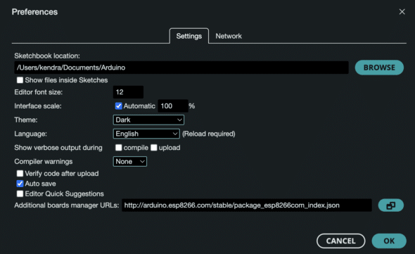
To get started, download the Arduino IDE Software. This environment makes the setup for flashing the board super simple and fast. For this specific board, you will need the ESP8266 Arduino library. To access this library in the IDE, go to Settings and add the URL in the “Additional boards manager URLs” field.
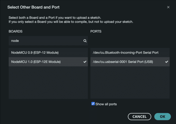
Next, configure the IDE for this board by opening the dropdown on the top left and choosing “Select other board and port.” Here you can choose the particular board and port. If you do not see the port for your board, make sure it’s plugged in. You also may need to give permission for the USB accessory to connect.
To ensure this setup is complete, try uploading a basic sketch to the board. I chose File -> Examples -> 01.Basics -> Blink. This provides the code for a basic blinky program which turns the onboard LED on for 1 second and off for 1 second in a continuous loop. Once you upload the sketch to the board by clicking the button in the top left corner of the IDE, you should see this blinking. If not, something has gone wrong.
Hardware Setup
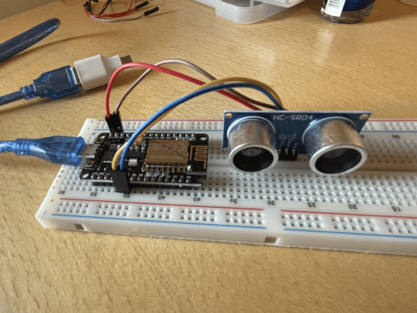
The hardware setup for this project is pretty simple as well. The ESP-12E controller comes with pins already soldered, so you can plug it in to a breadboard for prototyping. The HC-SR04 has four pins: GND, VCC, Trig, and Echo. You can provide power to the board using the controller by connecting the VCC and GND to the appropriate pins.
The other two pins on the ultrasonic sensor are used for initiating and reading distance. The Trig (Trigger) pin on the HC-SR04 ultrasonic distance sensor is used to initiate a measurement by sending a brief HIGH signal (typically 10 microseconds) to the sensor, which then emits an ultrasonic pulse. The Echo pin listens for the reflected ultrasonic wave, signaling a HIGH state while the wave travels back to the sensor; the duration that the Echo pin remains HIGH is measured to calculate the distance to the object, using the speed of sound. All this to say, they need to be connected to GPIO pins on the board. I chose pins D7 and D8.
Testing
To make sure everything worked correctly, I wrote the code in phases. First, I made sure the board could connect to Wi-Fi and communicate using HTTP. Then I added the code for the sensor. This sketch connects to Wi-Fi using the provided SSID (name of your Wi-Fi network) and password.
Test code for HTTP communication with the ESP8266:
#include

const char* ssid = "YOUR_SSID";
const char* password = "YOUR_PASSWORD";

WiFiServer server(80);

void setup()
{
    Serial.begin(115200);
    WiFi.begin(ssid, password);

    while (WiFi.status() != WL_CONNECTED)
    {
        delay(1000);
        Serial.println("Connecting to WiFi...");
    }

    Serial.println("Connected to WiFi");

    // Print the IP address assigned to the ESP8266
    Serial.print("IP Address: ");
    Serial.println(WiFi.localIP());

    server.begin();
}

void loop()
{
    WiFiClient client = server.available();

        if (client) {
        String currentLine = "";

        while (client.connected()) {
          if (client)
          {
            String currentLine = "";
              while (client.connected())
              {
                if (client.available())
                {
                  char c = client.read();
                  Serial.write(c);

                  if (c == '\n')
                  {
                    if (currentLine.length() == 0)
                    {
                        // Send response
                        client.println("HTTP/1.1 200 OK");
                        client.println("Content-type:text/html");
                        client.println();
                        client.print("Hello, world!");
                        break;
                    }
                    else
                    {
                        currentLine = "";
                    }
                }

                else if (c != '\r') {
                    currentLine += c;
                }
              }
            }
          }
        }
        client.stop();
    }
    delay(1000);
}
After you upload this sketch to the board, you will need to open a serial monitor to read the output from the board. I used the serial monitor integrated in the Arduino IDE, which is available under the “Tools” menu. Be sure to check the baud rate. It should be set to 115200 for this particular controller. Once the board connects to Wi-Fi it will print its IP Address. Navigate to this address in a browser, and you should see the text “Hello, world!”.
Once this is working, you can go ahead and integrate the code to read from the distance sensor. This sketch adds a function measureDistance which sets the Trig pin to HIGH to trigger the sensor and reads from the Echo pin to measure the distance read by the sensor. Distance is calculated by multiplying the duration by the velocity of sound / 2. For debugging purposes, this function also prints the result via the serial output.
Final sketch:
#include

const char* ssid = "YOUR_SSID"; // Your Wi-Fi SSID
const char* password = "YOUR_PASSWORD"; // Your Wi-Fi Password

const int trigPin = D7;
const int echoPin = D8;

//define sound velocity in cm/uS
#define SOUND_VELOCITY 0.034
#define CM_TO_INCH 0.393701

long duration;
float distanceCm;
float distanceInch;

WiFiServer server(80);

void setup()
{
    Serial.begin(115200);
    WiFi.begin(ssid, password);

    while (WiFi.status() != WL_CONNECTED)
    {
        delay(1000);
        Serial.println("Connecting to WiFi...");
    }

    Serial.println("Connected to WiFi");

    // // Print the IP address assigned to the ESP8266
    Serial.print("IP Address: ");
    Serial.println(WiFi.localIP());

    server.begin();

    // Initialize pins for ultrasonic sensor
    pinMode(trigPin, OUTPUT);
    pinMode(echoPin, INPUT);
}

void loop()
{
  delay(1000);
  measureDistance();

  WiFiClient client = server.available();

  if (client) {
    String currentLine = "";

    while (client.connected()) {
      if (client)
      {
        String currentLine = "";
        while (client.connected())
        {
          if (client.available())
          {
            char c = client.read();
            Serial.write(c);

            if (c == '\n')
            {
              if (currentLine.length() == 0)
              {
                // Send response
                client.println("HTTP/1.1 200 OK");
                client.println("Content-type:text/html");
                client.println();
                client.print("Distance: ");
                client.print(distanceCm);
                client.println(" cm");
                break;
              }
              else
              {
                currentLine = "";
              }
            }

            else if (c != '\r')
            {
              currentLine += c;
            }
          }
        }
      }
    }
    client.stop();
  }
  delay(1000);
}

void measureDistance()
{
  // Clears the trigPin
  digitalWrite(trigPin, LOW);
  delayMicroseconds(2);

  // Sets the trigPin on HIGH state for 10 micro seconds
  digitalWrite(trigPin, HIGH);
  delayMicroseconds(10);
  digitalWrite(trigPin, LOW);

  // Reads the echoPin, returns the sound wave travel time in microseconds
  duration = pulseIn(echoPin, HIGH);

  // Calculate the distance
  distanceCm = duration * SOUND_VELOCITY/2;

  // Convert to inches
  distanceInch = distanceCm * CM_TO_INCH;

  // Prints the distance on the Serial Monitor
  Serial.print("Distance (cm): ");
  Serial.println(distanceCm);
  Serial.print("Distance (inch): ");
  Serial.println(distanceInch);
}
Once you’ve flashed the board with this code, you can navigate again to the IP Address found in the previous step and see the output read from the distance sensor.
I ended the project here, but there’s a lot to build on. Now that I can measure distances and read this information over HTTP, I have a basis for many IoT projects. The possibilities are endless! What would you use this remote monitoring system for? Let me know in the comments, and it might become my next blog post!