When confronted with the idea of circuitry, what comes to mind? For many, the thought of handling electronics is very anxiety inducing. A stream of phrases come up often: “I’m terrible at math, so I wouldn’t be any good at that.” Or, “That stuff is basically magic.” And, of course, there’s the iconic, “I don’t want to cause an explosion or catch something on fire.”
These reactions are common and understandable, but they often act as self-imposed barriers to learning.
What if those mindsets are actually gatekeeping just how simple electronics can be in practice? In this post, I want to demystify the entry point into circuit design and show how quickly even the most basic circuits can become powerful tools. No fire and no explosions… okay, at least fewer explosions than electroBOOM (who teaches electrical safety the hard way on YouTube).
Required items
This guide will require you to have:
- Pencil, paper, and a basic calculator – cover the hairs on your neck – the math will be already done for you – but please, get creative
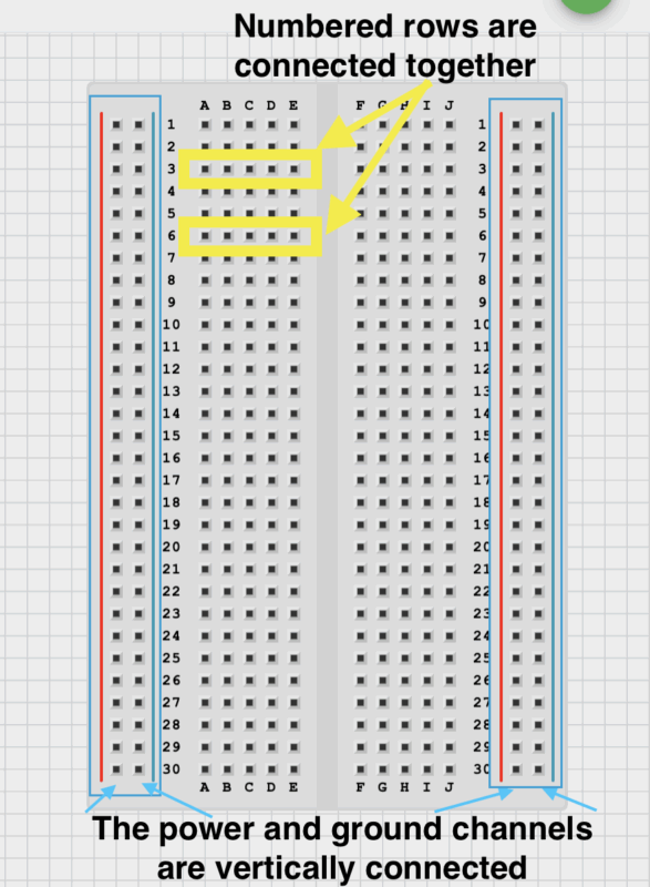
- Breadboard, jumper wires
- One blue, green, red, and yellow LED
- Resistors – I recommend buying a big ol` pack as they are very cheap and come in a wide variety
- Power supply (12 volts 1 Amp)
For 15$, here is a basic kit with a 9v power supply that could be used for the tutorial if you only power three LEDs.
Brief terminology
We will be wiring two separate circuits, both using all four LEDs.
The first will be wired in “series’ and the second in “parallel”.
Series: Parts are connected in one single path, so the same current flows through all of them. If one part breaks, everything stops working.
Parallel: Parts are connected on separate paths to the same power source, so each one works independently. If one part breaks, the others keep working.
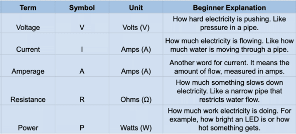
Voltage pushes, current flows, resistance restricts, power does the work.
LED information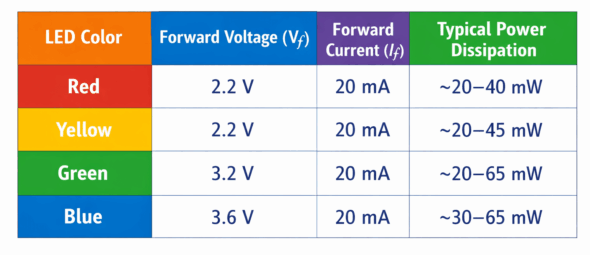
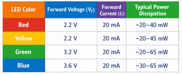
Before we calculate anything lets look at a of table regarding our LEDs and some additional common electrical terminology.
Notice the Forward Voltage (Vf column). The forward voltage is the minimum voltage needed for a component (like an LED or diode) to turn on and allow current to flow. When voltage passes through a component it takes uses up that amount of voltage from the power supply. For instance with a 12 V supply and a 3.6 V blue LED, about 3.6 V appears across the LED, leaving about 8.4 V for the rest of the circuit.
The Forward Current is the safe operating current at which that component can operate at. Meaning we should do a few calculations to make sure our LEDs don’t explode (they’ll just fizzle out if you give too much current they won’t actually explode don’t worry).
One simple calculation
There is only one equation that we are going to make use of in this guide but here are the fundamental formulas for circuitry. Not very scary right? For our purposes, only worry about the equation for resistance.
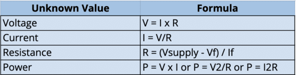
On quick reference from the table above, our blue LED has a forward voltage of 3.6 v and a forward current of 20 mA (0.02 Amps).
Considering we only care about finding a good resistor value for the blue LED, we will plug into the equation as follows.
Resistance = (12 V – 3.6 V) / 0.02 Amps
Resistance = 420 Ω (ohms)
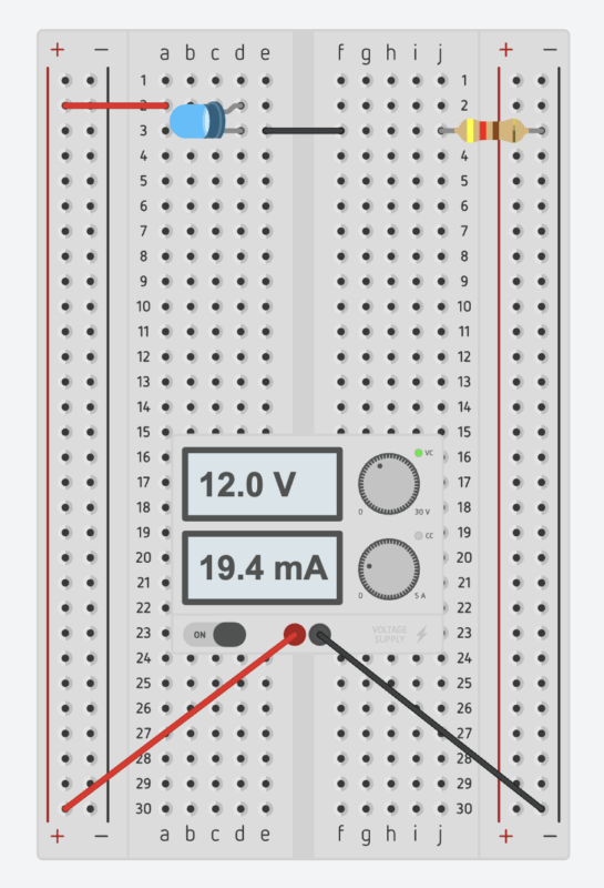
Connecting a single blue LED
This means that we require a 420 Ω resistor after connecting our blue LED in order for it to not spontaneously combust! Reference the images below to wire up your first circuit!
Series circuit
When using multiple LEDs, we can wire them in series or in parallel.
Wiring LEDs in series requires only one resistor (with our current power supply), which keeps the circuit simple. The drawback is that if one LED fails, they all turn off – very the same reason old Christmas lights go dark when a single bulb goes bad.
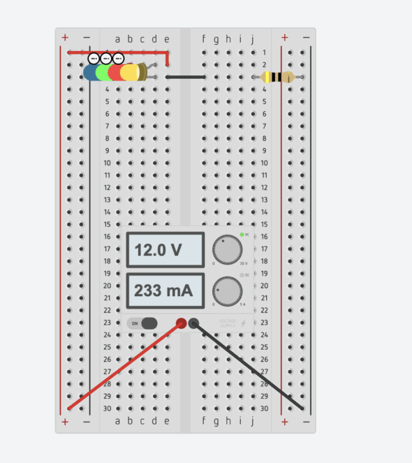
When we look at the wiring diagram, we see that the blue LED does not turn on. The 40 Ω resistor limits the current too much for the blue LED to light. We need a way to power all the LEDs at the same time.
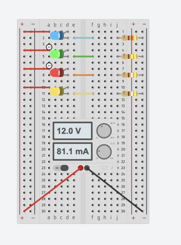
Parallel circuit
By choosing a parallel circuit, we give each LED its own resistor. Using our calculations, the resistor values are 420 Ω for blue, 440 Ω for green, and 490 Ω for both red and yellow.
I know this isn’t the “oh-so-powerful system” the title might suggest, but these fundamentals matter a lot. When you combine them with microcontrollers, motors, relays, sensors, and embedded code, you unlock endless possibilities.
Here’s a list of many common sensors, – let your creativity take it from there. If your creative juices didn’t wake up today consider reading Kendra Hann’s short blog: Build a MIDI Controller with Me Using Arduino or follow future articles for more advanced electronics!