You may have heard the news: Atomic Object is moving to a new building later this summer. We’re excited about designing the new space. For my part, I found an opportunity to try out a technology that I have not worked with before, the wireless networking system XBee.
In addition to migrating furniture, computers, and people down the street, we will also be moving an updated version of our “Callaloo” bathroom monitor system to our new home. This system, built by a former Atom, works as an occupancy sensor for each of our bathrooms, illuminating a green or red light on the wall to signify which bathrooms are available. Bathroom availability should not be a significant issue in the new space, but the monitor has become a useful and familiar part of our office. And looking forward, installing wireless mesh-network infrastructure will be a good experience: developing our “intranet of places” using current internet of things technology.
This blog post will cover the steps (and some background knowledge) needed for a basic XBee setup. The goal is to get two XBee modules to communicate. We’ll have a basic input (a button) on one side, which will remotely trigger an output (an LED) on the other side. This models the basic functionality of the overall Callaloo system: proximity sensors on the door (input) are transmitted to a receiving module that changes an output (indicator lights, server information) based on the data it receives.
Get to Know XBee
First, let’s talk about ZigBee*, a low-power wireless mesh network standard operating in the 2.4 GHz range. XBee is not the same as ZigBee—instead, XBee is a brand of radio communication modules (made by Digi) that can support a number of protocols, including ZigBee, 802.15.4, WiFi, etc. Its range is 10 to 30 meters. ZigBee is often used in home automation products, though it is not the only option.
*Bonus fact: ZigBee is named after the “waggle dance” that bees use to point other bees to food sources.
Gather Your Supplies
For this tutorial, I used:
- Two (2) Series 1 XBee Antenna Modules, available here
- Two (2) XBee Explorer USB Modules, available here, and USB cables
- Two (2) Arduino Unos and USB cables
- Two small breadboards (or one larger breadboard)
- Jumper wires
- Male headers (0.1”) to be soldered onto the Explorer modules
- One (1) 100 ohm resistor
- One (1) 5.1k ohm resistor
- One (1) button
- One (1) LED
- XCTU, available for download here
I chose Arduinos because I happened to have two on hand. You could use any dev boards that have a serial port.
Note: there are kits available for the XBee antenna and Explorer USB modules, such as this one from Trossen Robotics.
Configure Your XBees and Get ‘Em Talking
You will need to configure your XBee modules so they can communicate. The first part of this configuration involves setting the Channel, PAN ID, and Address values.
- Channel: The channel calibrates the operating frequency within the 2.4GHz 802.15.4 band. Your XBees must be on the same channel to communicate with one another.
- PAN ID (Personal Area Network ID): Your XBees must share the same PAN ID to communicate with one another. You can choose a value between 0 and 0xFFFF.
- Addressing: Each XBee has a source address (referred to as “MY address”) and a destination address (which has an upper half, Destination High or DH, and a lower half, Destination Low or DL). An XBee’s destination address specifies to which source address it can send data. You can specify a universally unique address by using the 64-bit address printed on the back of the module, use a shorter 16-bit address (unique within a network), or use a string of text (e.g., “Alice’s radio”).
Additionally, each XBee in a network plays a role. The three role options are Coordinator, End Device, and Router. Each network has exactly one Coordinator, which serves as the root of the network tree. A network can have multiple Routers; these can forward information to end devices and also run application functions. Lastly, End Devices cannot relay data, but only talk to a parent node (either a Coordinator or Router). A network can have multiple End Devices.
With that, let’s configure our XBees.
- Download and install XCTU. Available for both Windows and Mac.
- Plug your first XBee into an Explorer module, and connect to your computer’s USB port via a USB cable.
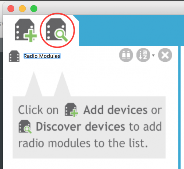
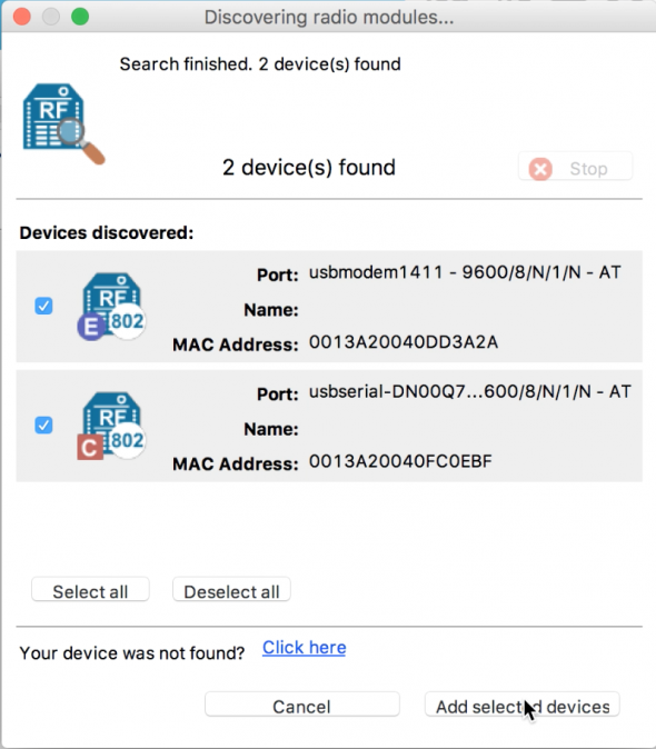
- Open XCTU and click “Discover devices.”
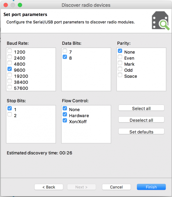
- Select the port to be scanned. Then on the next page, select the settings as shown below. Click “Finish.”
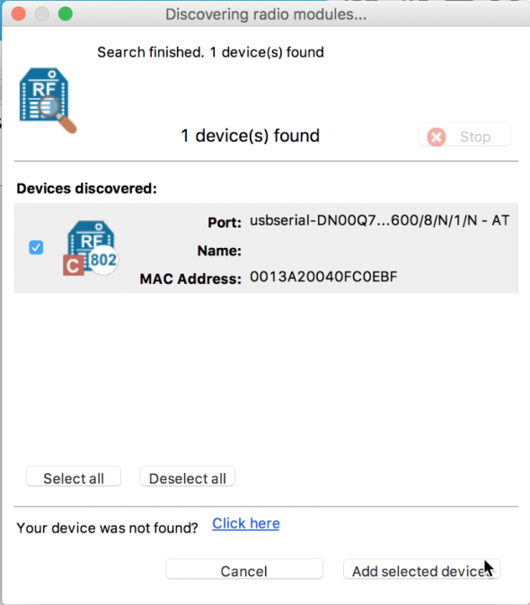
- Your device should appear on the “Devices discovered” list. Click “Add selected devices” for your module.
- With the Gear icon selected, click the radio module in the left-hand menu. This should open up a long list of settings.
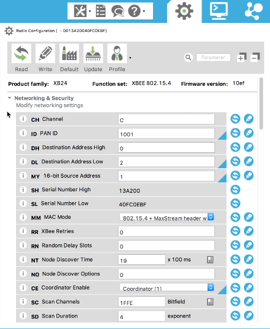
- Pick a channel (between 0x0 and 0xFFFF). Remember, each XBee must share the same channel number. I chose an arbitrary value of “0x0C.”
- Pick a PAN ID. As before, both modules must have the same number.
- For this simple demo, I went with the addressing configuration shown below (the 16-bit option from the address options previously discussed).
- Lastly, select “Coordinator” from the Coordinator Enable (CE) dropdown list. After you’ve made all your changes, click “Write.”
- Now unplug the first XBee, and repeat steps 2 through 10 with the second XBee, but with the addresses as shown in the second column of the table above. On this second XBee, you can leave the Coordinator Enable (CE) set as 0, or EndUser. I recommend you mark each module so you can easily tell them apart.
|
XBee Module #1
|
XBee Module #2
|
|
|
Destination High (DH)
|
0
|
0
|
|
Destination Low (DL)
|
2
|
1
|
|
MY Address
|
1
|
2
|
Run a Communication Test
- Now it’s time to see if they’ll talk. Plug one XBee (on its Explorer module) into a USB port (via USB cable), and plug the other XBee (on its Explorer module) into another USB port. In XCTU, scan for devices as before. You should see both devices available. Select both of them and click “Add selected devices.”
- Click one of the modules in the left-hand column. Now select the Console icon to view the console. Click “Open.”
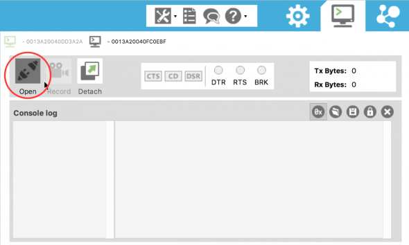
- Repeat for the other module, opening up a console.
- Type into one console. You should see the result echoed back in the other console. If so, congrats!
Set Up Your Circuits
The next step is to connect each XBee module to an Arduino, so we can connect our input (button) and output (LED). Again, this mimics the future bathroom monitor system, where inputs will be processed by a microcontroller and transmitted to a receiving microcontroller, which will change its outputs accordingly.
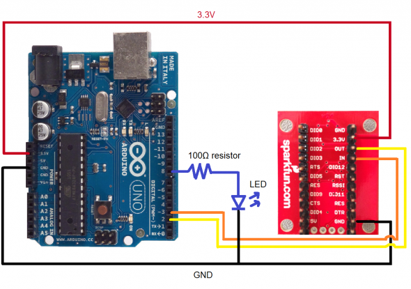
At this point, you will need to solder the headers on your Explorer boards. Connect the ground and 3.3V from the Arduino to the ground and power rails of your breadboard. Connect the power and ground rails of the breadboard to the 3.3V and GND pins on your Explorer module.
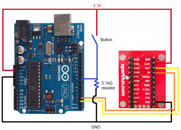
Next, connect the XBee Explorer pin OUT to Arduino pin 2 (RX), and XBee pin IN to Arduino pin 3 (TX). I chose to use the SoftwareSerial library and Arduino pins 2 and 3 (rather than the default pin 0 and 1 for serial communication), so that I could use the default serial pins for printing debug statements to a serial monitor.
Connect your button to the Arduino as shown in the diagram above. I wanted the button to default to logic low when not pressed, so I added a pull-down resistor to my circuit. If you don’t have a button, you can just use a piece of wire as your “switch,” connecting it to either power or ground.
Your first Arduino is now set up! To set up the other Arduino, repeat the connections for OUT, IN, 3.3V and GND. Connect the LED by connecting a wire from Pin 9 to the 100 ohm resistor, and then put in the LED. Make sure that the LED is in the right orientation. Remember that the shorter “leg” of the LED (the cathode) must be on the “ground” side.
At this point, I like to debug my circuit by writing a quick Arduino sketch to make sure that my LED and button are functioning as expected. Otherwise, I might conflate a communication issue with a simple wiring or port setting issue.
Write the Code
Using Arduinos makes the demo code fairly simple, although the final Callaloo will be a custom PCB design, not a pre-made development board (i.e., not using Arduino).
On the input (button) side, we are checking for a button input and writing a character to the XBee via a serial connection.
/* Input-side (button) Arduino code */
#include "SoftwareSerial.h"
// RX: Arduino pin 2, XBee pin DOUT.  TX:  Arduino pin 3, XBee pin DIN
SoftwareSerial XBee(2, 3);
int BUTTON = 8;

void setup()
{
  // Baud rate MUST match XBee settings (as set in XCTU)
  pinMode(BUTTON, INPUT);
  XBee.begin(9600);
}

void loop()
{
  if (digitalRead(BUTTON) == HIGH)
  {
    XBee.write('H');
    delay(50);
  }
}
On the output side, we are checking if we received a certain character, and if so, turning on the LED by setting that bit high.
/* Output-side (LED) Arduino code */
#include "SoftwareSerial.h"
// RX: Arduino pin 2, XBee pin DOUT.  TX:  Arduino pin 3, XBee pin DIN
SoftwareSerial XBee(2, 3);
int LED = 9;

void setup()
{
  // Baud rate MUST match XBee settings (as set in XCTU)
  XBee.begin(9600);
  pinMode(LED, OUTPUT);
}

void loop()
{
  if (XBee.available())
  {
    char c = XBee.read();
    if (c == 'H')
    {
      digitalWrite(LED, HIGH);
      delay(50);
    }
    else
    {
      digitalWrite(LED, LOW);
    }
  }
  else
  {
    digitalWrite(LED, LOW);
  }
}
Now you should have a basic XBee network up and running! The next step for the Callaloo system is to expand the XBee network with more modules and prototype the bathroom door sensors.
Hello Jaime,
This is great tutorial and I appriciate you.
Unfortunately I am very new on Xbee and I have 2 XBEE PRO S2C mode.
As far as I got from the enty,you used your antennas in transparent mode ?
When I select transparent mode none of the symbols for (C,R,E) are not appear.And I can not establish communication between two antennas.The loggs that I entered from the console,appear in the same console with different color.
What the problem is in your point of view ?
I hope I could explained well.
Thanks
what about the mode of xbee???
Thank you Jamie, I got some idea on X bee and I am trying on x bee pro 900 bhp modules for water tank automation , kindly share your ideas for communication between the said modules!
I like it very straight forward. I hope you will same tutorial but instead using NRF24L01 module
Its really very informative article. I found answer to a lot of my questions about xbee. Now its time to connect my recent bought xbees to explore their world. Many thanks Jamie.
Stavros
Hi very nice tutorial for Xbee if you can other one for xbee gateway will be kind from U
Hi your tutorial is very good for xbee we look for another one about xbee gateway please,,,
Can you explain the configuration settings of using 3 xbee (one coordinator and 2 End points). End point Xbee will be Sending information to the Coordinator. Please can u write a blog on it.
Good tutorial! Is it possible to connect two linux computers, like two raspberry pi or one rpi and one desktop, with this setup? I want to connect to computers, one on a robot and one for the users so the computer on robot can be monitored and controlled remotely.
Thanks,
Hello, I am trying to get two xbee’s talking via xctu however whenever I open up the serial consoles (one for transmitter, one for receiver), the only messages the receiver is receiving is “FF” which is the hex code for the space bar. Do you have any immediate solutions to this? Or any idea why the hex codes being sent are FF?
Good tutorial and helpful, but note that in your figure “Output side – (LED Circuit)” the LED is connected to pin #8. Your code for that end puts the LED on pin 9.
Your tutorial is a very nice way to get going on XBee. I’m looking now for a resource (other than the DIGI manual) ;-) to better explain the AP and AT command modes. My circuit is quite a bit like the Arduino shown above, but I’d like to poll the XBee to see how strong the RF connection is between them. I’m using older XBee Pro S1 models, which are still very available.
Hello Jaime
I thank you very much for your post.
I want to know if I can be able to developp software with a zigbee device that i don’t know the commands list just by learning trafic.
I want to buy thermostat: https://www.salusinc.com/wp-content/uploads/2017/11/OPTIMA_QSG-ENv3p1.pdf.
If i monitor the zigbee trafic, can I be able to developp software to send commands to this thermostat ?
thanks for your reply and best regards
Thierry Vorms
thats for the post its easy to understand the basics and start working not he first project.
Thanks for the Post its easy to understand the basics and start working on my first xbee project.