Article summary
This summer, I decided to explore home automation using a Raspberry Pi. I thought that it would be fun to control my garage door with Siri/iOS HomeKit and spent some time building a basic controller using JavaScript and some nice Node.js packages.
This post serves as the first in the series, each covering a different aspect of the build:
- Basic hardware acquisition and installation into a project box
- Software installation and code for controlling the door
- Software camera configuration and code streaming video to HomeKit
- Installing and configuring adding door open/closed sensors and adding an LCD status display
Hardware Acquisition
I purchased the items in the table below, which are required for opening and closing the garage door. You may be able to find them at a lower cost elsewhere, but I have included links to Amazon for your convenience. Also note that some items include more parts than are needed (breadboard, wires, etc.).
I ended up wiring the Raspberry Pi to my local network using Ethernet rather than Wi-Fi as it was out of the range of my home Wi-Fi. If you’d also like to do this, you’ll need the following items:
| Item | Purpose | Price |
|---|---|---|
| Leviton 5G108-RE5 GigaMax 5E QuickPort Connector, Cat 5E, Black | Providing external Ethernet port on project box | $4.48 |
| AmazonBasics RJ45 Cat-6 Ethernet Patch Cable – 3 Feet (0.9 Meters) | Attaching your project box to Ethernet switch | $4.99 |
| 0.5FT 24AWG Cat5e 350MHz UTP Bare Copper Ethernet Network Cable – Black | Attaching Raspberry Pi’s Ethernet port to external Ethernet port on project box | $3.18 |
I also found that I needed some other items during hardware installation:
| Item | Purpose |
|---|---|
| Phillips screwdriver | Attaching hardware to project box |
| Power drill and drill bit | Drilling holes in project box to attach standoffs |
| Small hand file | Trimming out plastic for mounting of USB power extension and Ethernet port |
| Drywall screws | Attaching project box to wall |
| Wire stripper | Cutting and stripping control wires |
| Needle-nose plyers | Bending control wires |
| Superglue | Attaching USB power extension and Ethernet port to project box |
| Small nuts/bolts | Attaching terminal block to project box |
Hardware Mounting and Installation
I’ve documented my build each step of the way through pictures and some instructions. You can follow along below.
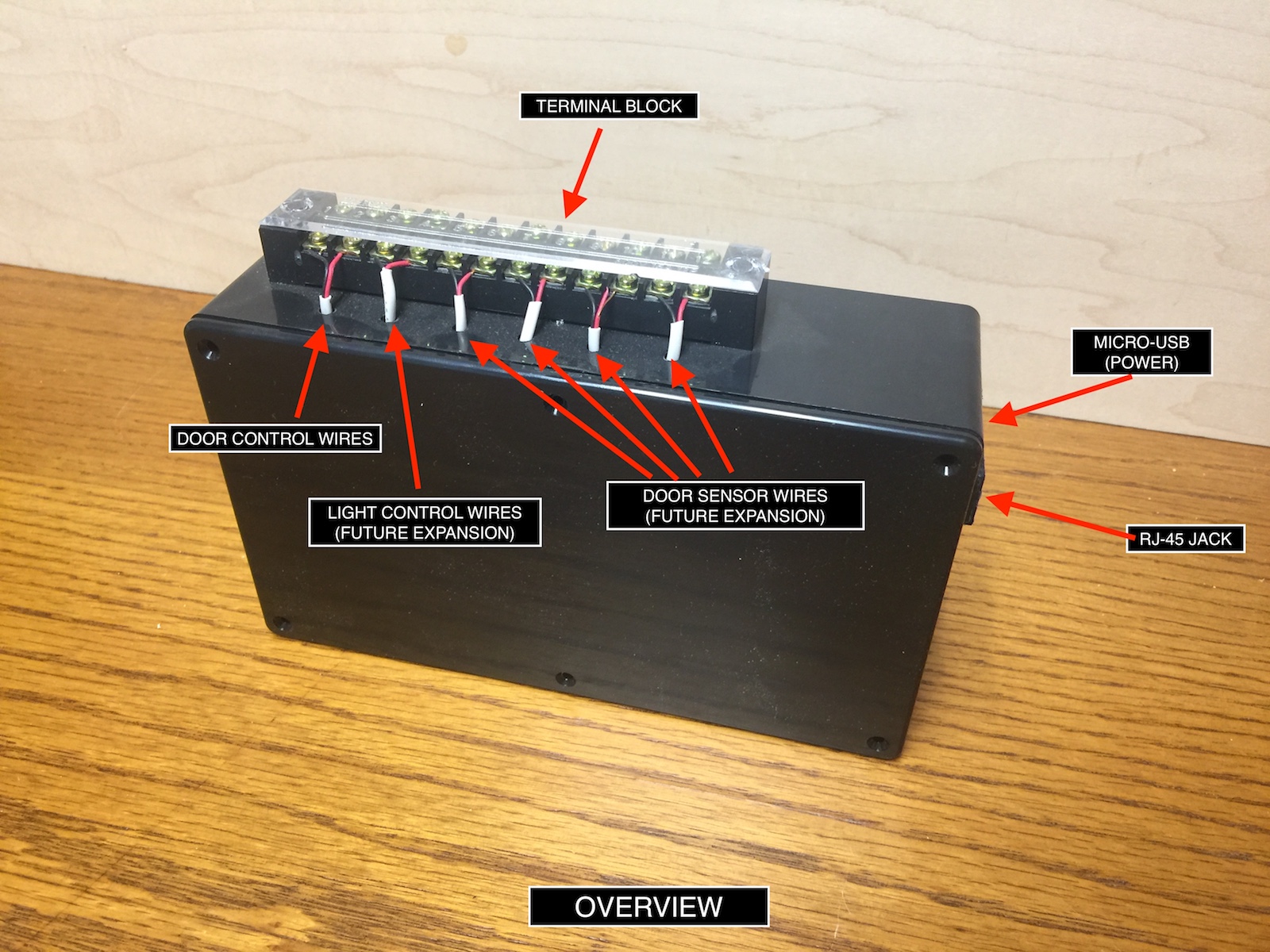
- Drill mounting holes for Raspberry Pi and relay in project box.
- Attach the Raspberry Pi using tall standoff mounts so you will have enough space to work with the breadboard.
- Attach the Relay using standoff mounts. In my case, I was able to superglue the bottom of the standoffs to the project box. You may want to drill and attach similarly to the Raspberry Pi. I plan to add the capability to monitor garage door open/closed status later. I left some room in the project box for a breadboard to accommodate this.
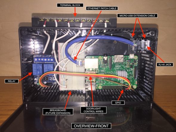
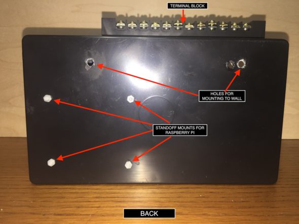
- Cut the short Ethernet patch cable on one end and wire into the RJ-45 jack. Leave the other end for connecting to the Raspberry Pi.
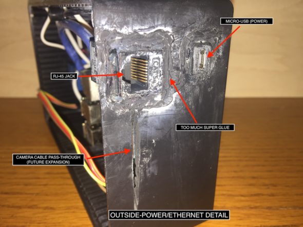
- Drill hole for mounting Micro USB extension cable in project box, then hand file the hole, making the opening large enough to fit extension cable.
- Drill hole for mounting Ethernet port in project box, then hand file the opening large enough to fit the port.
- Superglue each into place.
- Connect the Micro-USB extension to the incoming Micro USB port on the Raspberry Pi for power.
- Connect the short Ethernet patch cable to the RJ-45 jack on the Raspberry Pi.
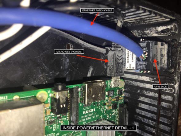

- Wire up a ground pin and 5V power pin from the GPIO on the Raspberry Pi to the GND and VCC on the relay, respectively.
- Wire up two GPIO pins on the Raspberry Pi to the IN1 and IN2 on the relay. You can use any two GPIO pins. In this case, we used GPIO 17 and GPIO 27.
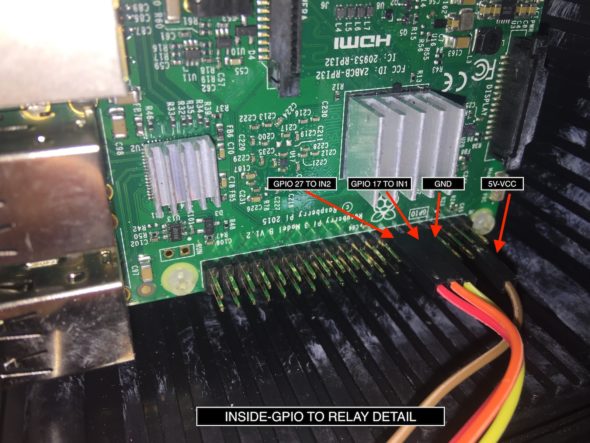
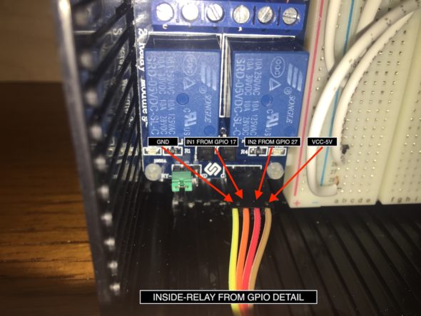
- Drill mounting holes for the terminal block and attach with two nuts and bolts. You may want to do this step earlier to avoid messy plastic shavings all over your components.
- Drill holes to pass through the control wires from the relay to the terminal block.
- Using 22-gauge wire, connect the K1 and K2 switches as shown in the photo to the first two and the second two.
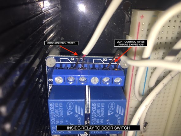
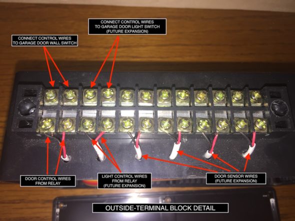
We now have a good foundation for our project. In the next part of this series, I’ll cover software installation, configuration, and code for controlling the the garage door open/close operation using the Raspberry Pi’s GPIO interface.

I’ve got a Genie PMX300IC/B opener that has three screws with wires going into it. They are labeled “Push Button”, “COM”, and “Safety Beam”. One pair of wires goes to the first two and the other pair goes to the second two. I assume that means my switch uses the first two screws and the child safety beam uses the last two. So, in your example, would I simply not have the K2 wire?
Is there someone that can make me one complete? I will pay obviously for your time. I have everything in my house homekit except the garage door. :-/
Have you ever played with a raspberry pi? Pretty fun, relatively simple, and tons of resources. I asked for more detailed pics inside the box but no reply yet. Prolly busy… I’d like to recommend a pi 3 and a sensor kit from amazon. Any will work and give you a better idea of what’s goin on. I’m no EE or programmer, only know just enough sql to be dangerous hehe have some more faith in yourself! :D it’s all about the journey and what’s learned on the way.
Hello,
Thanks for the detailed instructions. What would you suggest for 2 garage doors with 2 openers in the same house. I would love to build one but would like it for both garage doors?
Thanks for the instrucitons. Very cool. Curious if this works with Siri through CarPlay, or will Siri on CarPlay not pass through the relevant instructions?